5
DP20
A
NOMENCLATURE
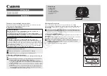
Camera Head
Any equipment connected to the camera head should be an Olympus-specified product or a
product in compliance with the requirements of IEC60950 or CISPR22/24. If equipment other
than these products is connected, Olympus cannot guarantee proper performance of the camera.
Control box connector (P. 9)
Threaded C-mount (P. 8)
Tripod adapter mount screw holes (P. 8)
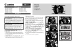
Control Box
*
Some buttons are shown with two functions per button. In this case, the function in the upper row indicates
that in REC mode and that in the lower row indicate that in PL AY mode.
*
SPOT button (P. 14)
*
PRINT button (P. 31)
INFO button (P. 13)
EXPOSE button (P. 16)
CF card slot (P. 11)
Compact Flush (CF card) Type I only.
Eject button (P. 11)
*
AE LOCK button (P. 14)
*
PROTECT button (P. 31)
AE LOCK indicator LED (P. 14)
OTWB button (P. 15)
ERASE button (P. 30)
Card access indicator LED (P. 11)
POWER indicator LED (P. 13)
MENU button (P. 17)
Main switch (P. 13)
MODE button (P. 13)
SET/OK button (P. 17)
Cross-cursor buttons (P. 17)