


3-56
3.12.2 LED Test
1. Press PROGRAM, *, B. Then press One-touch B. All LEDs will turn on.
Pressing START, toggle between All LEDs turn on and off.
2. Press STOP to exit the test mode.
3.12.3 LCD Test
This mode displays two test patterns in LCD.
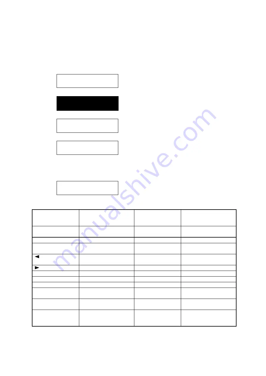
1. Press PROGRAM, *, B. Then press One-touch C.
LCD Test
Pressing START, all dots turn on.
Next pressing START, all dots turn off.
Finally pressing START, the alphabetical characters are shown in the LCD.
ABCDEFGHIJKLMNOPQRST
UVWXYZabcdefghijklmn
2. Press STOP to exit the test mode.
3.12.4 Key Panel Test
1. Press PROGRAM, *, B. Then press One-touch D.
Key Panel Test
2. As each button on the keypad is pressed, a representative name as show in the following table will
be displayed.
Key
Indication in LCD
Key
Indication in LCD
REVIEW
COMMAND
Review
BROADCAST
Broadcast
MONITOR CALL
Monitor/Call
COMMUNICATION
OPTIONS
Com. Option
RESOLUTION
Mode
GROUP DIAL
Group
CONTRAST
Contrast
SPEED DIAL
/TEL INDEX
Speed
/NEXT
<
MEMORY
TRANSMIT
Memory Transmit
/PROGRAM
>
BOOK DOC SIZE
Book Doc Size
ENTER
Enter
CLEAR ALL
Clear All
CANCEL
Cancel
STOP
Stop
REDUCT%
Reduc %
START
Start
ENLARGE%
Enlarge %
Numeric keys 0
through #
0 through #
SORT COPY
Sort Copy
One-touch keys 01
through 72
[01] through [72]
PAPER SIZE?
Paper size?
Programmable One-
touch keys 73
through 80
[73] through [80]
3. Press STOP twice to cancel the key panel test.
Содержание OKIOFFICE 120
Страница 7: ...vi ...
Страница 17: ...1 10 1 7 Dimensions Dimension in mm ...
Страница 23: ...1 16 1 11 ID Label Specification 1 12 Labels location ...
Страница 24: ...2 1 Section2 Machine Composition 2 1 Interconnect Block Diagram ...
Страница 25: ...2 2 ...
Страница 87: ...3 46 Unique Switch F 7 and F 9 Factory use only ...
Страница 190: ...5 60 Note If you re attach the feed roller B put the right and left nibs into the fixing hole as shown ...
Страница 195: ...5 65 10 Move the cassette PCB by sliding it 11 Disconnect the all connectors on the cassette PCB ...