


2-14
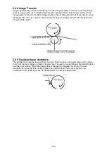
2.8.6 Fusing
An Overview
The toner image transferred on to the paper is securely fixed.
A heat roller system is used as the fusing system. The toner image is fused by Heater Roller heated
by the Heater Lamp, and securely fixed by the pressure between the Heater roller and Press rollers.
A Thermistor detects and controls the Heater Roller temperature.
The Thermostat functions when the Heater Lamp is not turned OFF even if the Thermistor detects a
high temperature malfunction.
Fusing Temperature Control Circuit
The Thermistor detects the surface temperature of the Heater Roller and inputs that analog voltage
into the Main Control PCB. Corresponding to this data, the Heater Lamp ON/OFF signal is output to
the Heater ON/OFF switch of the power supply unit, causing the Heater Lamp to turn ON or OFF to
control the fusing temperature.
When the Heater Lamp is not turned OFF even if the Thermistor detects a high temperature
malfunction, the thermostat shuts down the power to the heater lamp. When the thermostat is
malfunction, the thermal cut-off shuts down the power to the heater lamp.
Содержание OKIOFFICE 120
Страница 7: ...vi ...
Страница 17: ...1 10 1 7 Dimensions Dimension in mm ...
Страница 23: ...1 16 1 11 ID Label Specification 1 12 Labels location ...
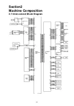
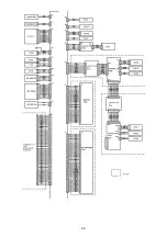
Страница 24: ...2 1 Section2 Machine Composition 2 1 Interconnect Block Diagram ...
Страница 25: ...2 2 ...
Страница 87: ...3 46 Unique Switch F 7 and F 9 Factory use only ...
Страница 190: ...5 60 Note If you re attach the feed roller B put the right and left nibs into the fixing hole as shown ...
Страница 195: ...5 65 10 Move the cassette PCB by sliding it 11 Disconnect the all connectors on the cassette PCB ...