


5-30
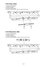
5.39 Feed roller assembly/Retard roller assembly
1. Remove the upper right cover.
2. Remove the book cover.
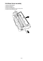
3. Remove the upper rear cover.
4. Remove the Tx cover.
5. Open the scanner cover.
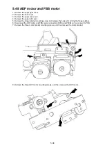
6. Remove the stopper.
7. Remove the gear cover.
8. Remove the inner guide B.
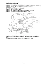
9. Remove the gear (47T) attaches above the feed roller assembly.
10. Remove the bearing, and then remove the feed roller assembly.
11. Remove the E-ring, and then remove the retard roller assembly.
Содержание OKIOFFICE 120
Страница 7: ...vi ...
Страница 17: ...1 10 1 7 Dimensions Dimension in mm ...
Страница 23: ...1 16 1 11 ID Label Specification 1 12 Labels location ...
Страница 24: ...2 1 Section2 Machine Composition 2 1 Interconnect Block Diagram ...
Страница 25: ...2 2 ...
Страница 87: ...3 46 Unique Switch F 7 and F 9 Factory use only ...
Страница 190: ...5 60 Note If you re attach the feed roller B put the right and left nibs into the fixing hole as shown ...
Страница 195: ...5 65 10 Move the cassette PCB by sliding it 11 Disconnect the all connectors on the cassette PCB ...


