-
18
-
PROCESSOR BOOSTER & CYLINDER
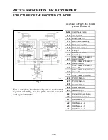
STRUCTURE OF THE BOOSTED CYLINDER
Fig. 1
For a complete breakdown of parts in the booster
cylinder assembly, see the parts manual for each
unit by serial number.
As shown in
Fig. 1
, the booster
cylinder consists of:
bs34
Inlet Check Valve
c11
Jaw Cylinder
c14
Booster Piston
c15
Main Valve Assembly
c17
Relief Valve (close)
c18
Relief Valve (open)
c19
Plunger
c20
Pilot Check Valve
Assembly
c21
Check Valve 1 - booster
piston inner "B"
c22
Check Valve 2 - booster
piston inner "A"
c23
Check Valve 3 - booster
sleeve "B"
c24
Check Valve 4 - booster
sleeve "A"
c25
Check Valve 5 - Return
c26
Port C1 Piston
c27
Port C2 Piston
c28
Port C3 Piston
c44
Swivel Manifold
c47
Small Plunger
k2
Carrier Hydraulic Pump
k7
Carrier Control Valve
v1
Oil Chamber - 1
v2
Oil Chamber - 2
v3
Oil Chamber - 3
v4
Oil Chamber - 4
Содержание M35G
Страница 13: ... 13 SERIAL NUMBER LOCATION M35 ...
Страница 115: ... 115 WARRANTY STATEMENTS ...
Страница 116: ... 116 WARRANTY STATEMENTS ...
Страница 118: ... Copyright 2018 NPK Construction Equipment Inc www npkce com M000 9601B M35 Material Processor Instruction Manual 10 18 ...


