background image

Vulcan Jet Dispensing System

Customer Product Manual

Part 1126187_05

Issued 09/21

NORDSON CORPORATION 

 DULUTH, GEORGIA 

 USA

www.nordson.com

This document contains important safety information.
Be sure to read and follow all safety information in this
document and any other related documentation.

Содержание Vulcan Jet

Страница 1: ...Manual Part 1126187_05 Issued 09 21 NORDSON CORPORATION DULUTH GEORGIA USA www nordson com This document contains important safety information Be sure to read and follow all safety information in this...

Страница 2: ...nature stylized Slautterback Smart Coat Smart Gun SolderPlus Sonolab Sonoscan Spectrum Speed Coat StediFlo Striped Hose Sure Coat SureBead SureWrap Symphony Tip Seal TRAK Tribomatic Trilogy TrueBlue T...

Страница 3: ...fety Warnings and Cautions 1 8 Other Safety Precautions 1 11 First Aid 1 11 Safety Labels and Tags 1 12 Description 2 1 Overview 2 1 Intended Use 2 2 Limitations of Use 2 2 Additional Limitations of U...

Страница 4: ...the Home Screen Navigation 4 14 Monitoring Input Output Statuses 4 15 Input Statuses 4 15 Output Statuses 4 18 Basic Operation and Controller Configuration 5 1 Overview 5 2 Special Operating Consider...

Страница 5: ...11 Modifying Cartridge Level Thresholds 6 11 Modifying Adhesive Lifetime Counter 6 12 System Settings 6 13 Modifying System Formats and Units 6 14 Modifying System Date and Time 6 15 Managing Applicat...

Страница 6: ...ater RTD Alarm Troubleshooting 8 2 Pressure Adhesive Alarm Troubleshooting 8 4 Input Output Alarm Troubleshooting 8 5 Storage Alarm Troubleshooting 8 8 System Board Alarm Troubleshooting 8 9 Temperatu...

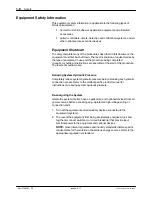
Страница 7: ...s document can result in personal injury including death or damage to equipment or property Safety Alert Symbols The following safety alert symbol and signal words are used throughout this document to...

Страница 8: ...governing regulations Contact the authority having jurisdiction for information S Maintain safety information including the safety labels affixed to the equipment in readable condition Instructions Re...

Страница 9: ...job function S are physically capable of performing their job function and are not under the influence of any substance that degrades their mental capacity or physical capabilities Applicable Industr...

Страница 10: ...ith the ATEX directive nor as nonincendive and should not be installed in potentially explosive environments S Ensure that the processing characteristics of the material will not create a hazardous en...

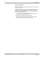
Страница 11: ...S Perform scheduled maintenance activities at the intervals described in this document S Relieve system hydraulic and pneumatic pressure before servicing the equipment S De energize the equipment and...

Страница 12: ...vels of shutdown are Relieving System Hydraulic Pressure Completely relieve system hydraulic pressure before breaking any hydraulic connection or seal Refer to the melter specific product manual for i...

Страница 13: ...pplicators applicator solenoid valve s or the melter pump must be disabled before work can be performed on or around an applicator that is connected to a pressurized system 1 Turn off or disconnect th...

Страница 14: ...rdson melter read and comply with the material s SDS Ensure that the material s processing temperature and flashpoints will not be exceeded and that all requirements for safe handling ventilation firs...

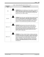
Страница 15: ...enoid valve s can result in personal injury HM CA PC WARNING Risk of electrocution Even when switched off and electrically isolated at the disconnect switch or circuit breaker the equipment may still...

Страница 16: ...nal injury HM CAUTION Some Nordson melters are specifically designed to process Polyurethane Reactive PUR hot melt Attempting to process PUR in equipment not specifically designed for this purpose can...

Страница 17: ...rst Aid If molten hot melt comes in contact with your skin 1 Do NOT attempt to remove the molten hot melt from your skin 2 Immediately soak the affected area in clean cold water until the hot melt has...

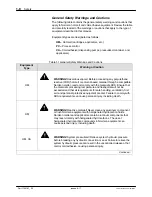
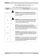
Страница 18: ...fety labels and tags affixed to the equipment Table 1 2 provides an illustration of the hazard identification symbols that appear on each safety label and tag the meaning of the symbol or the exact wo...

Страница 19: ...ed temperature When the system is activated it uses compressed air and jetting to dispense adhesive as a series of joined dots onto the surface of a product or into a product feature usually in a smal...

Страница 20: ...equipment must not be placed into use in a member state of the European Union until the parent machinery or assemblies have been declared by the integrator to be in conformity with the applicable dire...

Страница 21: ...Figure 2 2 You will need the model and part number of the applicator when requesting service or ordering spare parts and optional equipment The applicator model and part number are indicated on the e...

Страница 22: ...nd the location of key system components 7 9 6 8 2 4 1 5 3 Figure 2 3 Key components of the applicator and robot assemblies 1 Applicator 2 Air cap 3 Air supply inlet 4 Applicator controller output 5 A...

Страница 23: ...ption 2 5 Part 1126187_05 E 2021 Nordson Corporation 5 6 1 4 2 3 Figure 2 4 Pneumatic Kit Components 1 Air supply input 2 Air pressure controller 3 Flow solenoid 4 Flow sensor 5 Air output port 6 Air...

Страница 24: ...Description 2 6 Part 1126187_05 E 2021 Nordson Corporation Key Components contd 1 2 Figure 2 5 Vulcan Jet controller front view 1 Touch screen 2 Supports two per side...

Страница 25: ...or 6 E Stop Output 7 Flow solenoid output 8 Air controller output 9 Applicator piezo driver output 10 PUR cartridge level indicator 11 Control system status indicator OK Alert Fault 12 Flow sensor out...

Страница 26: ...Description 2 8 Part 1126187_05 E 2021 Nordson Corporation This page intentionally left blank...

Страница 27: ...the electrical and hydraulic connections Electromagnetic Compliance Information This system is classified as Class A Group 2 under the European standard for limits and methods of measurement EN 55011...

Страница 28: ...h Kit Part Number Item 1125557 Controller Assembly 1125686 Applicator Assembly 1125078 Pneumatic Kit 1125179 Applicator Piezo Cable 1125180 Applicator PCB Cable 1125181 Pressure Regulator Cable 112518...

Страница 29: ...ir Cables 4 Commissioning the Controller 5 Testing Purging the system for the first time Tools you will Need S 2 mm hex driver S 2 5 mm hex driver S 3 mm hex driver S 4 mm hex driver S Small flat head...

Страница 30: ...BOT Unity 2 3 AXIS 200 X 200 X 50 MM ROBOT Unity 3 3 AXIS 300 X 300 X 100 MM ROBOT Unity 4 3 AXIS 400 X 400 X 100 MM ROBOT Unity 5 3 AXIS 500 X 500 X 100 MM ROBOT Unity 4X 3 AXIS 400 X 400 X 100 MM RO...

Страница 31: ...ported robots 2 Gantry 3 Vulcan Jet Applicator Assembly 3 Using a 4 mm hex driver mount the Vulcan Jet bracket 1 to the supported robot gantry 2 Make sure the catch groove is facing up 4 Slide the app...

Страница 32: ...then twist it to indicate 4 When done push the knob back in S Using a small flat head screwdriver remove the solenoid connector 6 3 Connect the air kit main air supply input 1 to your primary air supp...

Страница 33: ...found on page 9 10 Step 3 Connecting the Controller and Air Cables 1 Refer to figure 3 3 Use the part numbers as a reference when connecting the seven cables S Make sure the main power supply is NOT e...

Страница 34: ...all Alarms and Warnings Equivalent to the Panel Reset function 18 Standby Control Active state causes the unit to go into Standby 20 Robot Ready Activated when the robot is ready to make products 14 G...

Страница 35: ...artridge heater Make sure the cartridge is flush with the top of the cartridge heater S Replace the air cap starting with the same 45 degree turn position The beveled top should be positioned opposite...

Страница 36: ...s optional for jetting but required to adjust the waveform S If you are making use of an unsupported robot or a parent machine make sure to have the E Stop wired to Pin 9 S The controller must be in a...

Страница 37: ...lcan Jet will make a loud sound while purging jetting The system should start jetting Wait until you see your cleaning or production adhesive come out of the applicator then toggle Purge Off 2 Congrat...

Страница 38: ...Installation 3 12 Part 1126187_05 E 2021 Nordson Corporation This page intentionally left blank...

Страница 39: ...ly qualified personnel to perform the following tasks Follow the safety instructions in this document and all other related documentation Overview The controller is shipped from the factory with most...

Страница 40: ...o heating zone set point temperatures S heat the adhesive cartridge to operating temperature S perform a stroke adjustment NOTE S Make sure to read and follow the instructions on the screen S The Comm...

Страница 41: ...the following primary screens S The Home screen S Master Controls screen S System Screen S Settings Screen About the Home Screen The Home screen is the default screen Counters Monitor Navigation Zone...

Страница 42: ...w state and status for each heated and pressure zones Counters S View the Lifetime Cycle Counter S View and pause resume the adhesive life timer S View and reset the Product Count S View and reset the...

Страница 43: ...6 Top Status Bar Ribbon Status Bar Figure 4 2 The Top Status Bar What the Controller Statuses Indicate The following table details the controller and zone pump status messages Reference number Top St...

Страница 44: ...ue On Ready Delay Although both the Cartridge and Nozzle zones are at set point temperatures the user has enabled the Ready Delay feature The system delays the Ready OK controller status for a user de...

Страница 45: ...ere you can reset the counter The controller continues to operate but servicing may be required 3 Current Status On or Off Needle Seat Service Reminder The defined service interval for number of cycle...

Страница 46: ...r Heaters Description 5 Current Status On or Off Security Indicates that security is not being enforced Security Indicates that security is being enforced Security Indicates that security is being enf...

Страница 47: ...necessary modify the system pressure Pressure Cartridge Nozzle 145_ C 145_ C 20 PSI Lifetime Cycle Counter Adhesive Life Timer Product Count Dot Count 1 000 000 000 4 40 20 8 About Pressure Statuses...

Страница 48: ...is true S The system itself and or one or both of the heated zones are in a fault condition S The system is either in the process of heating or the system is in Standby mode Pressure 15 PSI Red Fault...

Страница 49: ...ir set point temperatures very low S You cannot rename these two heated zones Pressure Cartridge Nozzle 145_ C 145_ C 20 PSI Lifetime Cycle Counter Adhesive Life Timer Product Count Dot Count 1 000 00...

Страница 50: ...an alert or fault condition S The system itself is in an alert or fault condition Zone 1 Alert Yellow Alert The system has detected an alert condition NOTE The controller continues to operate but att...

Страница 51: ...tinue The amount of time to elapse before the controller displays a Confirmation message asking you if you want to replace the cartridge now If you touch No the counter turns Yellow indicating that it...

Страница 52: ...form and to start the Stroke Adjustment Wizard S Modify Cartridge settings and options such as Level Thresholds the Adhesive Lifetime Counter Ready Delay as well as to start the Replace Calibrate Wiza...

Страница 53: ...inputs are hard wired and cannot be changed to indicate anything else Status Indicator Description The input is detected and or connected The input is undetected and or unconnected Settings Robot Read...

Страница 54: ...signal sources that switch the input to 0V 4 Decide if you want to drive the inputs with a relay or switch contact S Disable this control when connecting to a robot that is sourcing PNP 24V to prevent...

Страница 55: ...log 0 10V analog input Used to adjust the off time of the applicator 0 3V 3 ms 10V 10 ms NOTE This input must be enabled from the user interface before it is used 17 Applicator Home When active indica...

Страница 56: ...ed and or connected The output is undetected and or unconnected NOTE The Fault and Alert outputs are inverted meaning that if an Alert or Fault condition exits the corresponding indicator will be dimm...

Страница 57: ...Master Heater control is switched On and the Cartridge and Nozzle zones are at set point temperature 8 Product Complete When active indicates that a product has been completed This output stays activ...

Страница 58: ...About the Touch Screen and User Interface 4 20 Part 1126187_05 E 2021 Nordson Corporation This page intentionally left blank...

Страница 59: ...art 1126187_05 E 2021 Nordson Corporation Section 5 Basic Operation and Controller Configuration WARNING Allow only qualified personnel to perform the following tasks Follow the safety instructions in...

Страница 60: ...s in the Installation and Setup sections Special Operating Considerations for PUR Adhesive Because the viscosity of PUR adhesive increases significantly when the system is at operating temperature the...

Страница 61: ...ounter has elapsed S The adhesive level is low Note Refer to Replacing the Cartridge on page 5 6 for more information 5 The controller is ready for production when S The heated zones are at set point...

Страница 62: ...r WARNING Risk of burns When the last drops of adhesive are being purged the pressurized air will cause some adhesive spray Make sure that the collection pan is large enough to shield you from the spr...

Страница 63: ...m Master Controls On Off 1 From the Home screen touch Master 2 Touch the color coded button to switch On or Off the following Master Control Description Heater Control Manually switch the heaters On O...

Страница 64: ...from S The Vulcan Jet Home screen S The robot itself Dispenser Purge button on NOTE Refer to the previous section Overnight and Long Term Shutdown Procedures on page 5 4 for more information Replacing...

Страница 65: ...utton 2 Touch System Cartridge then Replace Calibrate The controller changes status from Ready OK to Heating and the Replace Calibrate Wizard starts Read and follow the instructions on the screen 3 Wh...

Страница 66: ...must be in a Ready OK state and the applicator in its Home position The following sections describe and detail each step in this process Modifying Zone Set Point Temperatures Refer to the SDS that ca...

Страница 67: ...m Maximum 20 PSI 5 PSI 50 PSI 1 38 Bar 0 34 Bar 3 45 Bar 137 90 kPa 34 47 kPa 344 74 kPa 175 C Pressure Pressure Set Point PSI 1 Access the Home screen and touch the pressure button 2 Enter the pressu...

Страница 68: ...ndard waveform S Optional waveform NOTE Use the standard waveform as a starting point If you do not achieve desired results try the optional waveform 1 From the Home screen do one of the following S T...

Страница 69: ...g information Waveform Control Description Dwell Time Controls the amount of time in ms that the applicator dispenses adhesive Closing Time Controls the amount of time in ms that it takes to stop disp...

Страница 70: ...he following information 2 Enter the following information Waveform Control Description Closing Time Controls the amount of time in ms that it takes to stop dispensing adhesive One Complete Cycle The...

Страница 71: ...ory S The controller retains the settings of the previously loaded recipe even if you delete or decide to not use a recipe Administration System Reset Display Save Diagnostics Reset Password Network R...

Страница 72: ...d enter an easily identifiable recipe name NOTES S To update the recipe settings enter the identical recipe name S The system unloads the currently loaded recipe then saves the new settings and automa...

Страница 73: ...ou want to import The system looks in the Recipes folder on the USB drive 3 Touch NOTES S This option is unavailable if the system cannot detect a USB drive S Only one recipe can be imported at a time...

Страница 74: ...led S Service Interval values S Numeric password code S Password Timeout value Standby Temperature Information Temperature and Pressure Zone Information S Standby Temperature S Standby enabled or disa...

Страница 75: ...o perform the following tasks Follow the safety instructions in this document and all other related documentation Overview The controller is shipped from the factory with most temperature pressure and...

Страница 76: ...e Settings S Defining cartridge level thresholds S Defining adhesive lifetime settings System Settings S Accessing system settings S Defining format and units S Defining data and time S Defining servi...

Страница 77: ...5 C 9 F 60 C 110 F Under Temperature Threshold 50 C 90 F 9 C 16 F 60 C 110 F NOTE When either an over or under temperature condition is detected the controller initially displays an Alert message You...

Страница 78: ...nly functions when the temperature of the Cartridge at the time the controller is turned On is more than 27 C 50 F from its set point temperature S The ready delay time begins when all components are...

Страница 79: ...tions in greater detail Using On Demand Standby You can enter into or exit out of Standby mode from the Master Controls screen NOTE Use this Master Standby control to also exit out of Manual Standby m...

Страница 80: ...atically exits Standby mode Item Default Minimum Maximum Manual Standby Off Auto Exit Standby Time 1 minute 1 minute 180 minutes Standby Settings Min Auto Exit Time Standby Time Enabled Disabled Manua...

Страница 81: ...ndby mode Default Minimum Maximum 50 C 90 F 5 C 10 F 60 C 110 F Global Set Point Temperature Limits Ready Delay Standby Global Set Point Temperature Limits Ready Delay Standby Standby Settings 5 min C...

Страница 82: ...ou replace the Needle Seat or Seal Pack components NOTE The system must be in a Ready OK status and not jetting otherwise All Applicator buttons are disabled Applicator Stroke Adjustment Input Wavefor...

Страница 83: ...Enabled Disable Bar Bar High Pressure Fault High Pressure Alert Applicator Stroke Adjustment Input Waveform Applicator Mode Applicator Mode Continuous Burst Number of dots 1 From the Home screen do on...

Страница 84: ...Fault condition S When purging the system uses this pressure set point along with the current Input Wave Form settings Default Minimum Maximum Disabled 2 PSI 0 5 PSI 5 PSI 0 14 Bar 0 03 Bar 0 34 Bar 1...

Страница 85: ...e Cartridge Wizard from either the Low or Empty alert message Default Minimum Maximum Empty Level Alert 0 mL 0 mL 1 mL Low Level Alert 5 mL 1 mL 20 mL Settings Cartridge Enabled Disable Enabled Cartri...

Страница 86: ...Wizard When done the controller automatically resets this timer S Refer to the Material Safety Sheet that came with the adhesive for more information S The Adhesive Life Timer is displayed on the Home...

Страница 87: ...ion System Settings The following sections detail S Modifying System Formats and Units S Modifying System Data and Time S Managing Applicator Service Reminders S Defining Language Preference S Definin...

Страница 88: ...ystem Formats Units Date Time Service Reminders Language System Security Display Administration System Information 07 14 15 2 37 PM English System Formats Units Date Time Service Reminders Language Sy...

Страница 89: ...mats Units Date Time Service Reminders Language System Security Display Administration System Information 07 14 15 2 37 PM English Date Time Settings Date Time PM 1 From the Home screen do one of the...

Страница 90: ...laced Item Default Minimum Maximum Seal Pack 40 Cycles million 20 Cycles million 100 Cycles million Needle Seat 100 Cycles million 20 Cycles million 200 Cycles million System Formats Units Date Time S...

Страница 91: ...e may be required Clear Reset Clear Melter Status indicator There are two ways to reset the service interval value From the pop up message Touch Description Clear Closes the pop up message but the ser...

Страница 92: ...utch S English S French S German S Italian S Japanese S Portuguese S Spanish System Formats Units Date Time Service Reminders Language System Security Display Administration System Information 07 14 1...

Страница 93: ...Maximum Brightness 75 30 100 Screen Saver Delay Enabled 5 minutes 1 minute 120 minutes Wipe Display 5 seconds System Formats Units Date Time Service Reminders Language System Security Display Adminis...

Страница 94: ...n saver only displays the melter status and its corresponding color To extend the lifespan of the touch screen itself the brightness is reduced from its current setting to 30 You can disable the Scree...

Страница 95: ...ministration System Information 07 14 15 2 37 PM English Min Password Timeout Change System Password Enabled Disabled System Security 1 From the Home screen do one of the following S Touch S Touch the...

Страница 96: ...access a screen or option on a screen Tip Instead of waiting for the Password Timeout you can touch the security icon to secure the controller and return to the Home screen What is Being Secured The...

Страница 97: ...r System Formats Units Date Time Service Reminders Language System Security Display Administration System Information 07 14 15 2 37 PM English HMI OS version 4 40 HMI Software version 4 55 Controller...

Страница 98: ...ng administration settings and options S Upgrading Downgrading Software and Firmware S Viewing the Event Log Save Diagnostics S Resetting to System Defaults Managing recipes S Resetting Password Codes...

Страница 99: ...drive into the USB port A pop up message box appears with the file that you want to use 3 Select the file that you want from the list and touch OK The touch screen displays a message stating Transfer...

Страница 100: ...drive regardless of what level of detail you selected S The event log can display up to 200 events after which the oldest event is overwritten with new events S You cannot clear nor change the name o...

Страница 101: ...ption to view Exit the event log Save File Save both the event log and the diagnostic file to the USB drive Touch this button only once Depending on the number of events in the log the save operation...

Страница 102: ...Save Diagnostics Reset System Password Recipes Network Configuration Lockout Communications Reset Network Password Disabled Enable Reset Options Service Reminders Lifetime Cycle Counter Are you sure y...

Страница 103: ...onfiguration Lockout Communications Reset Network Password Disabled Enable Reset Options Lifetime Cycle Counter Are you sure you want to reset the System Password to factory settings Yes No Confirm 1...

Страница 104: ...g or performing maintenance on the melter Administration System Reset Display Save Diagnostics Reset System Password Recipes Network Configuration Lockout Communication Disabled Enable 1 From the Home...

Страница 105: ...onfiguration Public IP Address Public IP Subnet Public Default Gateway 1 From the Home screen do one of the following S Touch S Touch Master then touch button 2 Touch System then touch Administration...

Страница 106: ...t Point 115_C 240_F Minimum 37 8_C 100_F Maximum 190_C 374_F Temperature Limits Over Temp 15_C 25_F Minimum 5_C 10_F Maximum 60_C 110_F Under Temp 25_C 50_F Minimum 9_C 16_F Maximum 60_C 110_F Auto St...

Страница 107: ...Enabled Disabled Pressure Compensation values 2 PSI 0 14 Bar 13 79 kPa Minimum 0 5 PSI 0 03 Bar 34 47 kPa Maximum 5 PSI 0 34 Bar 34 47 kPa Applicator Settings Setting Default Range Option Application...

Страница 108: ...minute Minimum 1 minute Maximum 60 minutes Adhesive Lifetime Counter 300 minutes Minimum 25 minutes Maximum 960 minutes Level Thresholds Empty 0 ml Minimum 0 ml Maximum 1 ml Low 5 ml Minimum 1 ml Max...

Страница 109: ...ange Option Display Brightness 75 Minimum 30 Maximum 100 Display Screen Saver Delay Enabled 5 minutes Minimum 1 minute Maximum 120 minutes Lockout Communications Off Off On Network Settings Setting De...

Страница 110: ...Advanced Controller Configuration 6 36 Part 1126187_05 E 2021 Nordson Corporation This page intentionally left blank...

Страница 111: ...icator Dwell Time Unsigned Short Applicator Dwell Time in Microseconds 50 200 40109 40110 W 16 bit Applicator Cycle Time Unsigned Short Applicator Cycle Time in Microseconds 3 000 10 000 40111 40112 W...

Страница 112: ...tage Unsigned Short Cartridge Level in Percent 0 100 40009 40012 R 32 bit Adhesive Life Unsigned Long Adhesive Life in seconds 40019 40020 R 16 bit System Status Unsigned Short 16 bits Bit 0 System Re...

Страница 113: ...0024 R 16 bit Piezo Driver Status Unsigned Short 16 bits Bit 0 Piezo Not Present Bit 1 Piezo Low Voltage Power Supply Fault Bit 2 Piezo High Voltage Power Supply Over Voltage Bit 3 Piezo High Voltage...

Страница 114: ...1 High Temperature Alert Bit 2 Zone 1 RTD Short Alert Bit 3 Zone 1 RTD Open Alert Bit 5 Zone 1 Write Temperature Set Point Invalid Alert 40014 R 8 bit Zone 2 Alerts Unsigned Char 8 bits Bit 0 Zone 2...

Страница 115: ...igned Short 8 bits Bit 0 Zone 1 Low Temperature Fault Bit 1 Zone 1 High Temperature Fault Bit 2 Zone 1 RTD Short Fault Bit 3 Zone 1 RTD Open Fault Bit 5 Zone 1 Run Away Temperature Fault 40018 R 8 bit...

Страница 116: ...cipe 12 Loading Recipe 13 Loading Recipe 14 Loading Recipe 15 Loading Recipe 16 Loading Unsigned Short 8 bits Note Only set 1 bit at a time Bit 0 Load RECIPE1 xml Bit 1 Load RECIPE2 xml Bit 2 Load REC...

Страница 117: ...art 1126187_05 E 2021 Nordson Corporation Section 7 Maintenance WARNING Allow only qualified personnel to perform the following tasks Follow the safety instructions in this document and all other rela...

Страница 118: ...aged parts pose a risk to the operational safety of the unit and or safety of personnel switch off the system and have the damaged parts replaced by qualified personnel Use only original Nordson spare...

Страница 119: ...t Controller must be in a Ready OK state 1 See Figure 7 1 Load a flush cartridge in the applicator as follows Remove the air cap 1 and remove and discard the adhesive cartridge 2 Remove the caps from...

Страница 120: ...use shut off the air supply at the regulator 4 Use a 3 mm hex wrench to loosen the mounting block screws 6 and slide the applicator out of the mounting block 7 5 Use a 2 mm hex wrench to loosen the t...

Страница 121: ...Maintenance 7 5 Part 1126187_05 E 2021 Nordson Corporation 1 2 3 5 4 4 6 7 8 Figure 7 2 General Disassembly...

Страница 122: ...4 2 5 Figure 7 3 Circuit Board Access 6 Use a 3 mm hex wrench to remove the two screws 1 that attach the mounting bracket to the top of the applicator Then remove the other two screws 2 that pass thro...

Страница 123: ...ator 1 from the frame 2 then remove the cartridge heater 3 and set these components aside NOTE Be careful to not damage cartridge heater wiring when removing cartridge 1 2 3 Figure 7 5 Actuator and Ca...

Страница 124: ...ck assembly 7 4 Grasp the applicator 1 and gently loosen the nozzle plate 4 using care to not damage the needle 8 and separate the nozzle plate from the heater block assembly 7 NOTE If you cannot sepa...

Страница 125: ...er in this section 2 Gently remove the old seal pack 5 by pulling downward with pliers CAUTION Do not contact the applicator needle The applicator will not operate as intended with a damaged needle If...

Страница 126: ...ts 1 You should have already done the following in this sequence S General Disassembly given earlier in this section S Removing the Nozzle Plate Assembly given earlier in this section S Removing the S...

Страница 127: ...ot have heating controls d Ensure that the seal pack has been removed from the nozzle plate then place the nozzle plate and heater block in an electric oven heated to approximately 385 _C 725 _F Allow...

Страница 128: ...g the Seal Pack given earlier in this section Cleaning the Applicator given earlier in this section 2 Remove the two screws 4 holding the heater block in place and remove the heater block 3 Using the...

Страница 129: ...stic needle housing 3 Make sure the top part of the needle housing is in contact with the bottom of the piezo actuator 2 Using the special needle removal tool rotate the needle clockwise until you fee...

Страница 130: ...e the applicator needle If No go to step 5 If Yes skip step 5 and refer to Removing the Applicator Needle given earlier in this section to continue 5 Lubricate the needle 1 2 3 4 5 Figure 7 10 Replaci...

Страница 131: ...ce in the nozzle plate assembly 5 3 Use a 2 5mm hex driver to sequentially tighten the two screws 6 that secure the nozzle plate 5 to the heater block 7 Torque the screws to a value of 8 9 in lb 4 Go...

Страница 132: ...embly given earlier in this section Refer to Cleaning the Applicator given earlier in this section Refer to Removing the Applicator Needle given earlier in this section 2 Place the applicator on a tab...

Страница 133: ...xchanger and put it aside 9 Slide the the piezo actuator 2 along with the slide block 3 and the air flush heat exchanger 4 up and out of the frame plates 1 1 3 2 1 4 5 Figure 7 14 Piezo Actuator Disas...

Страница 134: ...b 2 3 1 4 4 5 6 Figure 7 16 Piezo Actuator Assembly 3 Use a 2 5 mm hex wrench to tighten the two screws 2 that hold the air flush heat exchanger 3 to the slide block 5 Torque the screws to a value of...

Страница 135: ...e the two stroke adjustment screws 1 into and flush with the frame plate 3 NOTE To allow the slide assembly to move during stroke adjustment do not tighten these screws 11 Use a 2 5 mm hex driver to s...

Страница 136: ...n earlier in this section S Refer to Installing the Applicator Needle given earlier in this section S Refer to Installing the Seal Pack given earlier in this section S Refer to Installing the Nozzle P...

Страница 137: ...the applicator Torque the screws to a value of 8 9 in lb 1 2 Figure 7 21 Applicator Installation 4 Pivot the the circuit board mount bracket 5 to access the circuit board Connect the following wires t...

Страница 138: ...g a 2 mm hex wrench Tighten the three screws 4 that hold the applicator cover 9 on the applicator 8 1 2 3 5 4 6 7 9 4 8 Figure 7 23 General Assembly 7 Attach the following to the applicator a the air...

Страница 139: ...a 30 cc adhesive cartridge 3 b insert the cartridge in the applicator 8 with the tapered end pointing down c Install the air cap 2 10 Energize the controller then switch it On 11 Perform stroke adjus...

Страница 140: ...Cartridge Pressure Temperature Limits OT 25 C UT 50 F Pressure Cartridge Nozzle 145_ C 145_ C 20 PSI Lifetime Cycle Counter Adhesive Life Timer Product Count Dot Count 1 000 000 000 4 40 20 8 2 Touch...

Страница 141: ...Stroke Adjustment button on the Applicator screen Settings View Input Status Applicator Cartridge Temperature Limits View Output Status Applicator Stroke Adjustment Input Waveform Applicator Mode 4 Re...

Страница 142: ...Stroke If you completed the steps from the previous page then touch the Adjust Stroke button to continue 6 Review the two images and make sure the green is displayed on the screen Stroke Adjustment T...

Страница 143: ...problem with the information given here contact your local Nordson representative for help Overview Troubleshooting begins when the flow of adhesive from the applicator stops or diminishes unexpectedl...

Страница 144: ...on Heater RTD Alarm Troubleshooting Refer to the figure below and the following table to troubleshoot the alarms generated by the heater RTD 1 2 3 4 Figure 8 24 System Board Locations 1 Piezo driver 2...

Страница 145: ...rtridge Heater Current Overload Fault Cartridge heater current has exceeded the allowable limit Heater turned off Nozzle Heater Open Alert condition nozzle heater current has exceeded the allowable li...

Страница 146: ...Check Air pressure connection to the controller S Replace sensor transducer S Replace solenoid Low Pressure Fault The air pressure is below the alert threshold Cured Adhesive The cartridge has been in...

Страница 147: ...imit S HMI miswired S Defective cables S Check output wiring for incorrect connection S Check output wiring and cables for wear Replace cables as needed USB Power Supply Overload Alarm Power supply cu...

Страница 148: ...rect connection S Check output wiring and cables for wear Replace cables as needed S Replace I O PCA Pressure Dump Solenoid Power Supply Overload Alarm The air dump solenoid power supply current has e...

Страница 149: ...ected to the controller S Cable unplugged S Defective air pressure control valve S Defective I O PCA S Check replace cabling S Replace air pressure control valve S Replace I O PCA Open Thermocouple Ci...

Страница 150: ...le Error Corrupt File Alert Error reading file File is corrupt Reload file onto USB drive CRC File Error On Panel Fault Error verifying panel software Reinstall software using the archive recovery scr...

Страница 151: ...ards 1 2 3 4 Figure 8 25 System Board Locations 1 Piezo driver 2 I O board 3 Power distribution board 4 Communications board Table 8 5 System Board Alerts Faults Screen Message Effect on Controller Ca...

Страница 152: ...n S Perform a software upgrade S Perform a Factory Reset Maximum Internal Operating Temperature Exceeded Alert Internal temperature sensor reports that the internal operating temperature has been exce...

Страница 153: ...he board S Check diagnostic indicator lights on each board Software Upgrade Fail Fault The upgrade is unsuccessful S Power interruption while the upgrade is in progress S The file is not properly down...

Страница 154: ...RTD S Check for conditions that may cause an increase in ambient temperature S Replace the component S Install P N 1126121 Heat Exchanger Air Flush Kit See page 3 7 Undertemperature Alert condition T...

Страница 155: ...S Overload Fault HVPS overload fault inside the piezo driver board S Defective piezo actuator cable S Defective piezo actuator S Defective piezo driver S Replace piezo actuator cable S Replace piezo a...

Страница 156: ...oting Problem Possible Cause Corrective Action 1 Applicator does not heat System power not on Verify that the system power is turned on Loose electrical connection Verify that all electrical connectio...

Страница 157: ...lean the interface as needed Top of adhesive cartridge plugged Remove the cured layer of adhesive from the top of the adhesive cartridge 4 Bead too small Low input air supply Ensure that the input air...

Страница 158: ...the adhesive passages see Figure 8 1 and or replace the module Refer to Cleaning the Applicator under Maintenance Applicator temperature setpoint too low Increase the temperature setpoint Refer to Set...

Страница 159: ...part is not saleable In this case you must order either the assembly in which the part is used or a service kit that includes the part The Description column describes the part and sometimes includes...

Страница 160: ...art Description Quantity Note 1 1125686 VULCAN JET APPLICATOR 1 A 2 1125078 KIT PNEUMATIC VULCAN JET 1 B 3 1125557 VULCAN JET CONTROLLER 1 C 4 7407852 ROBOT UNITY 4XP 3AXIS 350 X 400 X 100MM 1 D NOTE...

Страница 161: ...T EPDM 2 19 463135 S plug type thread in ftg G D04 M5 0000 2 20 940261 S O RING VITON 1 250X1 375X 063 1 21 941151 S O RING VITON 688X 875X 094 10515 1 22 1125705 S SCREW SHOULDER 5X20XM4 SS 4 23 9828...

Страница 162: ...Parts 9 4 Part 1126187_05 E 2021 Nordson Corporation Figure 9 2 Vulcan Jet applicator parts...

Страница 163: ...Parts 9 5 Part 1126187_05 E 2021 Nordson Corporation Figure 9 3 Vulcan Jet applicator parts...

Страница 164: ...Parts 9 6 Part 1126187_05 E 2021 Nordson Corporation Vulcan Jet Applicator Parts See Figure 9 4 Item Part Description Quantity Note 1125078 KIT PNEUMATIC VULCAN JET Figure 9 4 Air kit parts...

Страница 165: ...NJET 1 03 1125592 S KIT BOTTOM PANEL ASSY VULCANJET 1 04 1125593 S KIT TOP PANEL ASSY VULCANJET 1 05 1125594 S KIT REAR PANEL ASSY VULCANJET 1 06 1122909 S CABLE USB TYPE A COUPLER FEMALE BULKHEAD 1 0...

Страница 166: ...Parts 9 8 Part 1126187_05 E 2021 Nordson Corporation 5 1 4 2 20 5 9 8 6 7 6X 19 3 Figure 9 5 Controller Assembly...

Страница 167: ...on Note 1034148 CABLEASSY DSUB 25POS M M 25FT not included 1125179 CABLE APPLICATOR PIEZO VULCAN JET 1125180 CABLE APPLICATOR PCB VULCAN JET 1125181 CABLE PRESSURE REGULATOR VULCAN JET 1125182 CABLE F...

Страница 168: ...A 1126067 KIT NEEDLE VULCANJET A 1126068 KIT PIEZO ACTUATOR VULCANJET 1126069 KIT O RINGS VULCANJET 1126070 KIT APPLICATOR PCA VULCANJET 1126071 KIT AIR CAP VULCANJET 1126072 KIT SYRINGE HEATER VULCA...

Страница 169: ...re sensitive and Ethylene Vinyl Acetate EVA hot melt adhesives and polyurethane reactive PUR adhesives excluding any compound that contains polyamides Electrical Specifications Component Item Specific...

Страница 170: ...Parts 9 12 Part 1126187_05 E 2021 Nordson Corporation Applicator Dimensions Figure 9 6 Vulcan Jet applicator dimensions in...

Страница 171: ......

Страница 172: ......

Отзывы: