6
2.2) Typical system
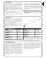
Figure 2 shows a typical system for automating a sliding gate using RUN.
2
1
Key-operated selector switch
2
Receiver FT210B
3
Photocells
4
Transmitter FT210B
5
Primary movable edge
6
“Open” limitswitch bracket
7
Rack
8
Flashing light with incorporated aerial
9
RUN
10
“Closed” limitswitch bracket
11
Primary movable edge (optional)
12
Radio transmitter
2.3) List of cables
The typical system shown in figure 2 also states the cables required for connection of the various devices, the specifications of which are
provided in table 5.
The cables used must be suitable for the type of installation; for example, an H03VV-F type cable is recommended for indoor
applications, while H07RN-F is suitable for outdoor applications.
!
Note 1:
power supply cable longer than 30 m may be used provided it has a larger gauge, e.g. 3x2,5mm
2
, and that a safety earthing sys-
tem is provided near the automation unit.
Note 2:
If the “BLUEBUS” cable is longer than 30 m, up to 50 m, a 2x1mm
2
cable is needed.
Note 3:
A single 4x0,5mm
2
cable can be used instead of two 2x0,5mm
2
cables.
Note 4:
Refer to Chapter “7.3.2 STOP Input” in situations where there is more than one edge, for information about the type of connection
recommended by the manufacturer.
Note 5:
special devices which enable connection even when the leaf is moving must be used to connect movable edges to sliding leaves;
con l'anta in movimento; nella figura è indicato l'utilizzo di FT210B.
Connection
Cable type
Maximum admissible length
A:
Electrical power line
N°1 cable 3x1,5mm
2
30m (note 1)
B:
Flashing light with aerial
N°1 cable 2x0,5mm
2
20m
N°1 shielded cable type RG58
20m (less than 5m recommended )
C:
Photocells
N°1 cable 2x0,5mm
2
30m (note 2)
D:
Key-operated selector switch
N°2 cable 2x0,5mm
2
(note 3)
50m
E:
Connection between 2 movable edges
N°1 cable 2x0,5mm
2
(note 4)
20m
F:
Movable edge connection
N°1 cable 2x0,5mm
2
(note 5)
30m
Table 5: List of cables
2
3
3
8
F
B
9
C
6
10
7
12
11
5
E
1
C
F
4
D
A


