background image

106

Índice:

pág.

1

Advertencias

107

2

Descripción del producto y uso previsto

108

2.1 

Límites de utilización

108

2.2

Instalación típica

110

2.3

Lista de cables

110

3

Instalación 111

3.1

Controles preliminares

111

3.2

Fijación del motorreductor

111

3.3

Fijación de los soportes de fin de carrera en las

versiones con fin de carrera de proximidad inductivo 112

3.4

Instalación de los diferentes dispositivos

113

3.5

Conexiones eléctricas

113

3.6

Descripción de las conexiones eléctricas

114

4

Controles finales y puesta en marcha 

114

4.1

Selección de la dirección

114

4.2

Conexión de la alimentación

114

4.3

Aprendizaje de los dispositivos

114

4.4

Aprendizaje de la longitud de la hoja

115

4.5

Control del movimiento de la puerta

115

4.6

Funciones predeterminadas

115

4.7

Receptor

115

5

Ensayo y puesta en servicio

115

5.1

Ensayo

116

5.2

Puesta en servicio

116

6

Mantenimiento y desguace

116

6.1

Mantenimiento

116

6.2

Desguace

116

7

Otras informaciones

117

7.1

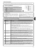
Botones de programación

117

7.2

Programaciones

117

7.2.1

Funciones de primer nivel (funciones ON-OFF) 117

7.2.2

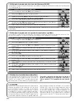
Programación de primer nivel 

(funciones ON-OFF)

118

7.2.3 

Funciones de segundo nivel 

(parámetros regulables)

118

7.2.4

Programación de segundo nivel 

(parámetros regulables)

119

7.2.5

Ejemplo de programación de primer nivel 

(funciones ON-OFF)

120

7.2.6 

Ejemplo de programación de segundo nivel 

(parámetros regulables)

120

7.3

Instalación o desinstalación de dispositivos

120

7.3.1

BlueBUS

120

7.3.2

Entrada STOP

121

7.3.3

Fotocélulas

121

7.3.4

Fotosensor FT210B

121

7.3.5

RUN en modo “Slave”

122

7.3.6

Aprendizaje de otros dispositivos

123

7.4

Funciones especiales

123

7.4.1

Función “Abrir siempre”

123

7.4.2

Función “Mover igualmente”

123

7.4.3

Sistema de control del calentamiento y 

refrigeración

123

7.4.4

Aviso de mantenimiento

123

7.5 

Conexión de otros dispositivos

124

7.6

Solución de los problemas

125

7.6.1

Listado del historial de los desperfectos

125

7.7

Diagnóstico y señales

125

7.7.1

Señales con la luz intermitente

126

7.7.2

Señales en la central

126

7.8

Accesorios 127

7.8.1

Unidad de Programación remota

127

8

Características técnicas

128

Instrucciones y advertencias para el usuario del 

motorreductor RUN

129

Run

1800/1800P
2500/2500P

Содержание RUN1800

Страница 1: ...r the fitter Istruzioni ed avvertenze per l installatore Instructions et recommandations pour l installateur Anweisungen und Hinweise für den Installateur Instrucciones y advertencias para el instalador Instrukcje i uwagi dla instalatora Aanwijzingen en aanbevelingen voor de installateur ...

Страница 2: ... 13 7 2 Programming 13 7 2 1 Level one functions ON OFF functions 13 7 2 2 Level one programming ON OFF functions 14 7 2 3 Level two functions adjustable parameters 14 7 2 4 Level two programming adjustable parameters 15 7 2 5 Level one programming example ON OFF functions 16 7 2 6 Level two programming example adjustable parameters 16 7 3 Adding or removing devices 16 7 3 1 BlueBUS 16 7 3 2 STOP ...

Страница 3: ...The automation system must not be used until it has been commis sioned as described in chapter 5 Testing and commissioning The RUN packaging materials must be disposed of in compliance with local regulations If a fault occurs that cannot be solved using the information provided in this manual contact the NICE customer service department In the event that any automatic switches are tripped or fuses...

Страница 4: ...oximity Maximum leaf length 15m Maximum leaf weight 1800Kg Peak thrust 50Nm corresponding to a force 1390N Motor Single phase asynchronous maximum 700W Table 1 comparison of the RUN gearmotor main characteristics 2 1 Operating limits Chapter 8 Technical Characteristics provides the only data needed to determine whether the products of the RUN line are suitable for the intended application The stru...

Страница 5: ...ements obtains a severity index equal to 45 20 15 10 From the graph the estimated durability is equal to 200 000 cycles Note that the estimated durability is calculated on the basis of design specifications and the results of tests performed on prototypes as this is an estimate only it does not represent any form of guarantee on the effective durability of the product RUN1800 RUN1800P RUN2500 RUN2...

Страница 6: ...s provided near the automation unit Note 2 If the BLUEBUS cable is longer than 30 m up to 50 m a 2x1mm2 cable is needed Note 3 A single 4x0 5mm2 cable can be used instead of two 2x0 5mm2 cables Note 4 Refer to Chapter 7 3 2 STOP Input in situations where there is more than one edge for information about the type of connection recommended by the manufacturer Note 5 special devices which enable conn...

Страница 7: ...ose specified in Chapter 8 Technical Characteristics The manufacturers recommend a 50 margin on the force as unfavourable climatic conditions may cause an increase in the friction Ensure that there are no points of greater friction in the opening or closing travel of the gate leaves Ensure there is no danger of the gate derailing Ensure that the mechanical stops are sufficiently sturdy and that th...

Страница 8: ...and Warnings for Users 8 9 10 11 6 Release the gearmotor as shown in Release and manual move ment paragraph in the Chapter Instructions and Warnings for users of the RUN gearmotor 7 Open the leaf up completely and place the first piece of the rack on the pinion Check that the beginning of the rack corresponds to the beginning of the leaf as shown in Figure 8 Leave 1 2 mm play between the rack and ...

Страница 9: ...brane back in its seat Place a second clamp for collect ing the cables which are set just above the membrane 4 On the smaller membrane cut a hole slightly smaller than the diameter of the power cable and slide the membrane along the cable until it fits into its seat 5 Connect the power cable to the relative terminal as shown in fig ure 14 and secure the cable by means of the collar 6 Connect up th...

Страница 10: ...uvre must be chosen according to the position of the gearmotor with respect to the leaf If the leaf must move to the left for opening the selector must be moved towards left as shown in Figure 17 alternatively if the leaf has to move to the right during opening the selector must be moved towards the right as shown in Figure 18 17 18 4 2 Power supply connection The connection of RUN to the mains mu...

Страница 11: ... that the flashing light flashes at a speed of 0 5 seconds on and 0 5 seconds off If present also check the flashes of the light connected to the open gate indica tor terminal slow flashes during opening quick flashes during closing 4 Open and close the gate several times to make sure that there are no points of excessive friction and that there are no defects in the assembly or adjustments 5 Chec...

Страница 12: ...tions for the release and manual manoeuvre 4 Prepare the declaration of conformity of the automation system and deliver it to the owner 5 Prepare the Instructions and warnings for the use of the automa tion system and deliver it to the owner 6 Prepare the maintenance schedule of the automation system and deliver it to the owner this must provide all directions regarding the maintenance of the sing...

Страница 13: ...ged After 5 seconds the gate will begin to close automatically The Close after photo function is always disabled in manoeuvres interrupted by a Stop command If the Close after photo function is inactive the pause time is that which has been programmed or there is no automatic closing if the function is inactive L3 Always Close The Always Close function is activated causing closure when an open gat...

Страница 14: ... memorize the modifications made up to that stage 1 Press and hold key Set approx 3 s 3s 2 Release the Set key when L1 LED starts flashing L1 3 Press keys or to move the flashing LED onto the LED representing the function to be changed o 4 Press the Set key to change the state of the function short flashing OFF long flashing ON 5 Wait 10 seconds before leaving the programme to allow the maximum ti...

Страница 15: ...al opening Par tial opening can be controlled with the 2nd radio command or with CLOSE if the Clo se function is present this becomes Partial open Adjusts the number of manoeuvres after which it signals the maintenance request of the automation see paragraph 7 4 4 Main tenance warning The type of defect that has occurred in the last 8 manoeuvres can be established see paragraph 7 6 1 Malfunctions ...

Страница 16: ...logy enables the connection of compatible devices using only two wires which carry both the power supply and the communication signals All the devices are connected in parallel on the 2 wires of the BlueBUS itself It is not necessary to observe any polarity each device is individually recognized because a univocal address is assigned to it during installation Photocells safety devices control keys...

Страница 17: ...s TX RX must comply with the provisions contained in the photocell instruction manual 7 3 3 Photocells By means of addressing using special jumpers the BlueBUS sys tem enables the user to make the control unit recognise the photo cells and assign them with a correct detection function The addressing procedure must be performed both on TX and RX set ting the jumpers in the same way making sure ther...

Страница 18: ...ion as Slave or Master when choosing one must consider the convenience of the connections and the fact that the Step by Step command of the Slave only allows the Slave leaf to be opened fully Connect the 2 motors as shown in fig 26 Select the opening direction of the 2 motors as shown in fig 25 see also paragraph 4 1 Choosing the direction Supply power to the 2 motors Program the Slave mode on the...

Страница 19: ... on the Open Gate indicator output when this is programmed as a Maintenance Indicator see table 9 The flashing light Flash and the maintenance light give the signals indicated in table 16 based on the number of manoeuvres per formed according to the limits programmed 7 4 Special functions Table 14 RUN Slave programming independently from RUN Master Level one functions ON OFF functions Level two fu...

Страница 20: ...0 of the manoeuvres has not yet been reached 8 Release the key Set Table 17 check of the number of manoeuvres performed Example SET SET SET SET n Manoeuvre counter reset After the maintenance of the system has been performed the manoeuvre counter must be reset Proceed as described in table 18 1 Press and hold Set approx 3 s 3s 2 Release Set when led L1 starts flashing L1 3 Press key or to move the...

Страница 21: ...hat there is voltage on the flashing light s FLASH terminal during the manoeu vre being intermittent the voltage value is not important approximately 10 30Vdc if there is voltage the problem is due to the lamp in this case replace the lamp with one of the same characteristics if there is no voltage there may have been an overload on the FLASH output Check that the cable has not short circuited Che...

Страница 22: ...uring the self learning phase One or more devices may be faulty check and if necessary replace them in case of modifi cations repeat the self learning process 7 3 4 Self learning Other Devices 7 7 1 Flashing light signalling During the manoeuvre the flashing light FLASH flashes once every second When something is wrong the flashes are more frequent the light flashes twice with a pause of a second ...

Страница 23: ...ed for leaf length self learning phase refer to Paragraph 4 4 Leaf length Self learning On Flashing Off On Flashing During normal operation indicates Thrust active Function programming in progress On Lampeggia During normal operation indicates Pre flash not active During normal operation indicates Pre flash active Function programming in progress Off On Flashing Led L7 Description During normal op...

Страница 24: ...d in table 4 Maximum power absorption on start up corresponding to Amps 700 W 3 A 5 A version V1 Power at nominal torque corresponding to Amps 400 W 1 8 A 3 A version V1 Insulation class 1 safety earthing required Flashing light output For 2 Flashing lights LUCYB lamp 12V 21W BLUEBUS output One output with maximum load of 15 BlueBus units Gate open indicator output For 1 24V lamp of maximum 4W out...

Страница 25: ...d with detection devices that prevent move ment if people or objects are in the way guaranteeing safe and reliable activation However children should not be allowed to play in the vicinity of automated systems to prevent any accidental activations keep all remote controls away from children they are not toys Malfunctions If you notice that your automation is not functioning properly disconnect the...

Страница 26: ...time seems not to work as well or not to work at all it may simply be that the battery is exhausted depending on the type of use it may last from several months up to one year and more In this case you will see that the light confirming the transmission is weak or does not come on or comes on only briefly Before calling the installation technician try exchanging the battery with one from another o...

Страница 27: ......

Страница 28: ...zioni primo livello funzioni ON OFF 39 7 2 2 Programmazione primo livello funzioni ON OFF 40 7 2 3 Funzioni secondo livello parametri regolabili 40 7 2 4 Programmazione secondo livello parametri regolabili 41 7 2 5 Esempio di programmazione primo livello funzioni ON OFF 42 7 2 6 Esempio di programmazione secondo livello parametri regolabili 42 7 3 Aggiunta o rimozione dispositivi 42 7 3 1 BlueBUS ...

Страница 29: ... di pericolo L automatismo non può essere utilizzato prima di aver effettuato la messa in servizio come specificato nel capitolo 5 Collaudo e messa in servizio Il materiale dell imballaggio di RUN deve essere smaltito nel pieno rispetto della normativa locale Nel caso di guasto non risolvibile facendo uso delle informazioni ripor tate nel presente manuale interpellare il servizio di assistenza NIC...

Страница 30: ...o di prossimità induttivo Lunghezza massima anta 15m Peso massimo anta 1800Kg Coppia massima allo spunto 50Nm corrispondenti a forza 1390N Motore Asincrono monofase 700W massimo Tabella 1 comparazione caratteristiche essenziali motoriduttore RUN 2 1 Limiti d impiego I dati relativi alle prestazioni dei prodotti della linea RUN sono ripor tati nel capitolo 8 Caratteristiche tecniche e sono gli unic...

Страница 31: ... pari al 45 20 15 10 Dal grafico la durabilità stimata è 200 000 cicli Si precisa che la stima di durabilità viene fatta sulla base dei calcoli progettuali e dei risultati di prove effettuate sui prototipi essendo una sti ma non rappresenta alcuna garanzia sulla effettiva durata del prodotto RUN1800 RUN1800P RUN2500 RUN2500P Peso dell anta kg Percentuale cicli Percentuale cicli Fino a 500 100 500 ...

Страница 32: ...essaria una messa a terra di sicurezza in prossimità dell automazione Nota 2 se il cavo BLUEBUS è più lungo di 30m fino ad un massimo di 50m occorre un cavo 2x1mm2 Nota 3 i due cavi 2x0 5mm2 possono essere sostituiti da un solo cavo 4x0 5mm2 Nota 4 se è presente più di un bordo vedere il paragrafo 7 3 2 Ingresso STOP per il tipo di collegamento consigliato Nota 5 per il collegamento dei bordi mobi...

Страница 33: ...le forze perché le condizioni climatiche avverse possono far aumentare gli attriti Verificare che in tutta la corsa del cancello sia in chiusura che in apertura non ci siano punti con maggiore attrito Verificare che non vi sia pericolo di deragliamento dell anta e che non ci siano rischi di uscita dalle guide Verificare la robustezza degli arresti meccanici di oltre corsa con trollando che non vi ...

Страница 34: ...zioni ed avvertenze destina te all utilizzatore 8 9 10 11 6 Sbloccare il motoriduttore come indicato nel paragrafo Sblocco e movimento manuale sul capitolo Istruzioni ed avvertenze destinate all utilizzatore del motoriduttore RUN 7 Aprire completamente l anta appoggiare sul pignone il primo tratto di cremagliera e verificare che l inizio della cremagliera cor risponda all inizio dell anta come in ...

Страница 35: ...e la membrana nella sua sede Porre una seconda fascetta per raccogliere i cavi appena sopra la membrana 4 Sulla membrana più piccola ritagliare un foro un po più stretto del diametro del cavo di alimentazione ed infilare la membrana lungo il cavo fino a reinserirla nella sua sede 5 Collegare il cavo di alimentazione da rete sull apposito morsetto e bloccarlo con l apposito collarino come indicato ...

Страница 36: ...ecessario scegliere la direzione della manovra di apertura se per l apertura l anta deve muovere verso sinistra occorre spostare il selettore verso sinistra come in figura 17 se per l apertura l anta deve muovere a destra occorre spostare il selettore a destra come in figura 18 17 18 4 2 Allacciamento dell alimentazione L allacciamento dell alimentazione a RUN deve essere eseguito da personale esp...

Страница 37: ...ficare che il lampeggiante effettui i lam peggi con periodi di 0 5s acceso e 0 5s spento Se presente controllare anche i lampeggi della spia collegata al morsetto S C A lampeggio lento in apertura veloce in chiusura 4 Effettuare varie manovre di apertura e chiusura con lo scopo di evidenziare eventuali difetti di montaggio e regolazione o altre anomalie come ad esempio punti con maggior attrito 5 ...

Страница 38: ...na targa con indicate le operazioni per lo sblocco e la manovra manuale 4 Realizzare e consegnare al proprietario la dichiarazione di confor mità dell automazione 5 Realizzare e consegnare al proprietario il manuale di Istruzioni ed avvertenze per l uso dell automazione 6 Realizzare e consegnare al proprietario il piano di manutenzione dell automazione che deve raccogliere tutte le prescrizioni su...

Страница 39: ...resta subito dopo il disimpegno delle fotocellule e si provoca la richiusura automatica con una pausa di 5s La funzione di Richiudi Dopo Foto viene sempre disabilitata nelle manovre interrotte con un comando di Stop Se la funzione Richiudi Dopo Foto non è attiva il tempo di pausa sarà quello programmato o non ci sarà richiusura automatica se la funzione non è attiva L3 Chiude Sempre La funzione Ch...

Страница 40: ...o a quel momento 1 Premere e tener premuto il tasto Set per circa 3s 3s 2 Rilasciare il tasto Set quando il led L1 inizia a lampeggiare L1 3 Premere i tasti o per spostare il led lampeggiante sul led che rappresenta la funzione da modificare o 4 Premere il tasto Set per cambiare lo stato della funzione lampeggio breve OFF lampeggio lungo ON 5 Attendere 10s per uscire dalla programmazione per fine ...

Страница 41: ...la la misura dell apertura parziale L apertura parziale si può comandare col 2 comando radio oppure con CHIUDE se c è la funzione Chiude diventa Apre Parziale Regola il numero di manovre dopo il quale segnalare la richiesta di manutenzione del l automazione vedere paragrafo 7 4 4 Avviso di Manutenzione Permette di verificare il tipo di anomalia intervenuta nelle ultime 8 manovre vedere paragrafo 7...

Страница 42: ...vi 7 3 1 BlueBUS BlueBUS è una tecnica che permette di effettuare i collegamenti dei dispositivi compatibili con soli due conduttori sui quali transita sia l a limentazione elettrica che i segnali di comunicazione Tutti i disposi tivi vengono collegati in parallelo sugli stessi 2 conduttori di BlueBUS e senza necessità di rispettare alcuna polarità ogni dispositivo viene riconosciuto singolarmente...

Страница 43: ...iportata nel manuale di istruzioni delle fotocellule 7 3 3 Fotocellule Il sistema BlueBUS consente tramite l indirizzamento con gli appositi ponticelli il riconoscimento delle fotocellule da parte della centrale e di assegnare la corretta funzione di rilevazione L opera zione di indirizzamento va fatta sia sul TX che sul RX ponendo i pon ticelli nello stesso modo verificando che non vi siano altre...

Страница 44: ...ura 25 È indifferente quale motore funziona come Master e quale come Sla ve nella scelta occorre valutare la comodità dei collegamenti ed il fatto che il comando Passo Passo sullo Salve consente l apertura totale solo dell anta Slave Collegare i 2 motori come in figura 26 Selezionare la direzione della manovra di apertura dei 2 motori come indicato nel paragrafo 4 1 Selezione della direzione Alime...

Страница 45: ...m peggiante Flash oppure sulla lampada collegata all uscita S C A quando è programmata come Spia Manutenzione vedere tabella 9 In base al numero di manovre eseguite rispetto al limite programma to il lampeggiante Flash e la spia manutenzione danno le segnala zioni riportate in tabella 16 7 4 Funzioni particolari Tabella 14 programmazioni su RUN Slave indipendenti da RUN Master Funzioni di primo li...

Страница 46: ...Rilasciare il tasto Set Tabella 17 verifica del numero di manovre effettuate Esempio SET SET SET SET n Azzeramento contatore manovre Dopo aver eseguito la manutenzione dell impianto è necessario azzerare il contatore delle manovre Procedere come descritto in tabella 18 1 Premere e tener premuto il tasto Set per circa 3s 3s 2 Rilasciare il tasto Set quando il led L1 inizia a lampeggiare L1 3 Premer...

Страница 47: ...i lità inferiore Verificare che durante la manovra vi sia tensione sul morsetto FLASH del lampeggiante essendo intermittente il valore di tensione non è significativo circa 10 30Vcc se c è tensione il problema è dovuto alla lampada che dovrà essere sostituita con una di uguali caratteristiche se non c è tensione potrebbe essersi verificato un sovraccarico sull uscita FLASH verificare che non vi si...

Страница 48: ...ante la fase di apprendimento E possibile vi siano dispositivi guasti verificare e sostituire se sono state fatte delle modifiche occorre rifare l apprendimento 7 3 4 Apprendimento altri dispositivi 7 7 1 Segnalazioni con il lampeggiante Il segnalatore lampeggiante FLASH durante la manovra esegue un lampeggio ogni secondo quando accadono delle anomalie vengono emessi dei lampeggi più brevi i lampe...

Страница 49: ...a lunghezza dell anta vedere paragrafo 4 4 Apprendimento lunghezza dell anta Acceso Lampeggia Spento Acceso Lampeggia Durante il funzionamento normale indica Spunto attivo Programmazione delle funzioni in corso Acceso Lampeggia Durante il funzionamento normale indica Prelampeggio non attivo Durante il funzionamento normale indica Prelampeggio attivo Programmazione delle funzioni in corso Spento Ac...

Страница 50: ...orbita allo spunto cor rispondenti ad Ampere 700 W 3 A 5 A versione V1 Potenza alla coppia nominale corrispondenti ad Ampere 400 W 1 8 A 3 A versione V1 Classe di isolamento 1 è necessaria la messa a terra di sicurezza Uscita lampeggiante per 2 lampeggianti LUCYB lampada 12V 21W Uscita BLUEBUS una uscita con carico massimo di 15 unità BlueBus Uscita S C A per 1 lampada 24V massimo 4W la tensione d...

Страница 51: ... bambini di giocare in prossimità dell automazione e per evita re attivazioni involontarie non lasciare i telecomandi alla loro portata non è un gioco Anomalie Non appena notate qualunque compor tamento anomalo da parte dell automazione togliete alimentazione elettrica all impianto ed eseguite lo sblocco manuale Non tentate da soli alcuna ripara zione ma richiedete l intervento del vostro installa...

Страница 52: ...gio oppure non funzionare affatto potrebbe semplicemente dipendere dall esaurimento della pila a seconda dell uso possono trascorrere da diversi mesi fino ad oltre un anno Ve ne potete accorgere dal fat to che la spia di conferma della trasmissione non si accende è fioca oppure si accende solo per un breve istante Prima di rivolgervi all installatore provate a scambiare la pila con quella di un al...

Страница 53: ......

Страница 54: ...ons du premier niveau fonctions ON OFF 65 7 2 2 Programmation du premier niveau fonctions ON OFF 66 7 2 3 Fonctions de deuxième niveau paramètres réglables 66 7 2 4 Programmation du deuxième niveau paramètres réglables 67 7 2 5 Exemple de programmation de premier niveau fonctions ON OFF 68 7 2 6 Exemple de programmation de deuxième niveau paramètres réglables 68 7 3 Ajout ou retrait de dispositifs...

Страница 55: ...ilisation de RUN dans de telles circonstances peut créer des situations de danger L automatisme ne peut pas être utilisé avant d avoir effectué la mise en service comme l explique le chapitre 5 Essai et mise en service Les matériaux d emballage de RUN doivent être mis au rebut dans le plein respect des normes locales en vigueur En cas de pannes qui ne peuvent pas être résolues avec les informa tio...

Страница 56: ... Poids maximum du tablier 1800Kg Couple maximum au démarrage 50Nm correspondant à la force 1390N Moteur Asynchrone monophasé 700 W maximum Tableau 1 comparaison des caractéristiques essentielles des opérateurs RUN 2 1 Limites d utilisation Les données relatives aux performances des produits de la ligne RUN figurent dans le chapitre 8 Caractéristiques techniques et sont les seules valeurs qui perme...

Страница 57: ...ique la durabilité estimée est de 200 000 cycles Il faut préciser que l estimation de durabilité s effectue sur la base des calculs de projet et des résultats des essais pratiqués sur les prototypes s agissant d une estimation elle ne constitue en aucun cas une garantie de la durée effective du produit RUN1800 RUN1800P RUN2500 RUN2500P Poids du tablier kg Pourcentage de cycles Pourcentage de cycle...

Страница 58: ...2 et une mise à la terre est nécessaire à proximité de l automatisme Note 2 si la longueur du câble BLUEBUS dépasse 30 m jusqu à un maximum de 50m il faut un câble de 2x1mm2 Note 3 les deux câbles de 2x0 5mm2 peuvent être remplacés par un unique câble 4x0 5mm2 Note 4 s il y a plus d un bord sensible voir le chapitre 7 3 2 Entrée STOP pour le type de connexion conseillée Note 5 pour la connexion de...

Страница 59: ...lle une marge de 50 sur les forces car les conditions climatiques adverses peuvent accroître les frictions Vérifier que dans la course du portail aussi bien en fermeture qu en ouverture il n y a pas de points présentant une plus grande friction Vérifier que le tablier ne risque pas de dérailler ni de sortir des rails de guidage Vérifier la robustesse des butées mécaniques de limitation de la cours...

Страница 60: ...ions et recomman dations destinées à l utilisateur 8 9 10 11 6 Débrayer l opérateur suivant les indications du paragraphe Débrayage et manœuvre manuelle dans le chapitre Instructions et recommandations destinées à l utilisateur de l opérateur RUN 7 Ouvrir complètement le tablier poser sur le pignon le premier seg ment de crémaillère et vérifier que le début de la crémaillère cor respond au début d...

Страница 61: ...Mettre un deuxième collier de serrage pour regrouper les câbles juste au dessus de la membrane 4 Sur la membrane la plus petite découper un trou un peu plus étroit que le diamètre du câble d alimentation et enfiler la membrane le long du câble jusqu à ce qu elle soit de nouveau en place 5 Connecter le câble d alimentation du secteur sur la borne corres pondante et le bloquer avec le collier prévu ...

Страница 62: ...tion de l opérateur par rapport au tablier si le tablier doit coulisser vers la gauche pour l ouverture il faut mettre le sélecteur vers la gauche comme sur la figure 17 si le tablier doit coulisser vers la droite pour l ouverture il faut mettre le sélecteur vers la droite comme sur la figure 18 17 18 4 2 Branchement au secteur Le branchement de RUN au secteur doit être effectué par du personnel e...

Страница 63: ...eture 3 Durant la manœuvre vérifier que le clignotant clignote à une fré quence régulière de 0 5 s S il est présent contrôler également les clignotements du voyant connecté à la borne S C A clignote ment lent en ouverture rapide en fermeture 4 Effectuer différentes manœuvres d ouverture et de fermeture pour mettre en évidence les éventuels défauts de montage et de régla ge ou d autres anomalies co...

Страница 64: ...age et la manœuvre manuelle 4 Remplir et remettre au propriétaire la déclaration de conformité de l automatisme 5 Rédiger et remettre au propriétaire de l automatisme la notice Ins tructions et avertissements pour l utilisation de l automatisme 6 Rédiger et remettre au propriétaire le plan de maintenance de l au tomatisme qui doit regrouper toutes les prescriptions pour la maintenance de chaque di...

Страница 65: ...ture automatique commence La fonction de refermeture après passage devant la photocellule est toujours désactivée dans les manœuvres interrompues avec une commande de Stop Si la fonction refermeture après passage devant la photocellule n est pas active le temps de pause sera celui qui est programmé ou bien il n y aura pas de refermeture automatique si la fonction n est pas active L3 Ferme toujours...

Страница 66: ...automatiquement en mémorisant les modifications faites jusqu à ce moment là 1 Presser et maintenir enfoncée la touche Set pendant environ 3 s 3s 2 Relâcher la touche Set quand la LED L1 commence à clignoter L1 3 Presser les touches ou pour déplacer la LED clignotante sur la LED qui correspond à la fonction à modifier ou 4 Presser la touche Set pour changer l état de la fonction clignotement bref O...

Страница 67: ...ou verture partielle peut se commander unique ment avec la 2e commande radio ou bien avec FERMETURE si la fonction est pré sente fermeture devient alors ouverture partielle Règle le nombre de manœuvres au bout duquel il faut signaler la demande de main tenance de l automatisme voir paragraphe 7 4 4 Avis de maintenance Permet de vérifier le type d anomalie qui s e st vérifiée au cours des 8 dernièr...

Страница 68: ...positifs 7 3 1 BlueBUS BlueBUS est une technique qui permet d effectuer les connexions des dispositifs compatibles avec seulement deux conducteurs sur lesquels transitent aussi bien l alimentation électrique que les signaux de com munication Tous les dispositifs sont connectés en parallèle sur les 2 mêmes conducteurs de BlueBUS sans devoir respecter une polarité quelconque chaque dispositif est re...

Страница 69: ...ellules 7 3 3 Photocellules Le système BlueBUS permet à travers l adressage avec les cava liers prévus à cet effet la reconnaissance des photocellules de la part de la logique et d attribuer la fonction de détection correcte L opération d adressage doit être faite aussi bien sur TX que sur RX en plaçant les cavaliers de la même manière en vérifiant qu il n y a pas d autres paires de photocellules ...

Страница 70: ... peut choisir l un ou l autre moteur comme Master et comme Slave dans le choix il faut tenir compte de la commodité des connexions et du fait que la commande Pas à pas sur le Slave per met l ouverture totale uniquement de la partie commandée par le moteur Slave Connecter les 2 moteurs comme sur la figure 26 Sélectionner le sens de la manœuvre d ouverture des 2 moteurs comme l indique le paragraphe...

Страница 71: ... A quand il est programmé comme voyant maintenance voir tableau 9 Suivant le nombre de manœuvres effectuées par rapport à la limite programmée le clignotant Flash et le voyant de maintenance don nent les signalisations indiquées dans le tableau 16 7 4 Fonctions particulières Tableau 14 programmations sur le RUN Slave indépendantes du RUN Master Fonctions de premier niveau fonctions ON OFF Fonction...

Страница 72: ...n clignotement 8 Relâcher la touche Set Tableau 17 vérification du nombre de manœuvres effectuées Exemple SET SET SET SET n Mise à zéro du compteur des manœuvres Après avoir effectué la maintenance de l installation il faut mettre à zéro le compteur des manœuvres Procéder suivant les indications du tableau 18 1 Presser et maintenir enfoncée la touche Set pendant environ 3 s 3s 2 Relâcher la touche...

Страница 73: ... du clignotant com me il est intermittent la valeur de tension n est pas significative environ 10 30 Vcc si la tension arrive le problème est dû à l ampoule qui devra être remplacée par une autre de caractéristiques identiques s il n y a pas de tension il pourrait y avoir un problème de surcharge sur la sortie FLASH vérifier qu il n y a pas de court circuit sur le câble Vérifier le type de fonctio...

Страница 74: ...t la phase de reconnaissance Il peut y avoir des dispositifs en panne vérifier et remplacer si des modifications on été faites il faut refaire la reconnaissance 7 3 4 Reconnaissance d autres dispositifs 7 7 1 Signalisations avec le clignotant Durant la manœuvre l indicateur clignotant FLASH émet un clignotement toutes les secondes quand des anomalies se vérifient les cligno tements sont plus brefs...

Страница 75: ...ffectuer la reconnaissance de la longueur du tablier voir paragraphe 4 4 Reconnaissance de la longueur du tablier Allumée Clignote Éteinte Allumée Clignote Durant le fonctionnement normal elle indique fonction démarrage active Programmation des fonctions en cours Allumée Clignote Durant le fonctionnement normal elle indique fonction Préclignotement non active Durant le fonctionnement normal elle i...

Страница 76: ...ance maximum absorbée au démarrage correspondant à ampères 700 W 3 A 5 A version V1 Puissance au couple nominal correspondant à ampères 400 W 1 8 A 3 A version V1 Classe d isolation 1 la mise à la terre est nécessaire Sortie clignotant pour 2 clignotants LUCYB Ampoule 12 V 21 W Sortie BLUEBUS Une sortie avec charge maximum de 15 unités BlueBus Sortie S C A pour 1 ampoule 24 V maximum 4 W la tensio...

Страница 77: ...dent toutefois de ne pas laisser jouer les enfants à proximité de l automatisme et pour éviter les activations involontaires de ne pas laisser à leur portée les émetteurs qui commandent la manœuvre ce n est pas un jeu Anomalies si vous notez une anomalie quelconque dans le fonctionnement de l automatisme coupez l ali mentation électrique de l installation et procédez au débrayage manuel Ne tentez ...

Страница 78: ... ou ne fonctionne plus du tout cela pourrait dépendre tout simplement du fait que la pile est usée suivant l intensité d utilisation il peut s écouler plusieurs mois jusqu à plus d un an Vous pou vez vérifier cet état de chose si le voyant de confirmation de la transmission est faible s il ne s allume plus du tout ou s il ne s allume qu un bref instant Avant de vous adres ser à l installateur essa...

Страница 79: ......

Страница 80: ...nktionen des ersten Niveaus ON OFF Funktionen 91 7 2 2 Erstes Niveau Programmierungen ON OFF Funktionen 92 7 2 3 Funktionen des zweiten Niveaus einstellbare Parameter 92 7 2 4 Zweites Niveau Programmierungen einstellbare Parameter 93 7 2 5 Erstes Niveau Programmierungsbeispiel ON OFF Funktionen 94 7 2 6 Zweites Niveau Programmierungsbeispiel einstellbare Parameter 94 7 3 Hinzufügen oder Entfernen ...

Страница 81: ...m die Inbe triebsetzung ausgeführt wurde wie in Punkt 5 Abnahme und Inbe triebsetzung vorgesehen Das Verpackungsmaterial muss unter voller Einhaltung der örtlichen Vorschriften entsorgt werden Wenn ein Defekt mit den im vorliegenden Handbuch gegebenen Infos nicht beseitigt werden kann wenden Sie sich bitte an den NICE Kun dendienst Wenn Automatikschalter oder Sicherungen ausgelöst werden muss vor ...

Страница 82: ...icht des Tors 1800Kg Höchstdrehmoment beim Anlauf 50Nm entspricht der Kraft 1390N Motor einphasiger Asynchronmotor max 700 W Tabelle 1 Vergleich der wichtigsten Merkmale des Toröffners RUN 2 1 Einsatzgrenzen Die Leistungsdaten der Produkte der Linie RUN sind in Kapitel 8 Technische Merkmale angegeben sie ermöglichen als einzige Wer te eine korrekte Bewertung der Eignung der Produkte Dank der struk...

Страница 83: ...selemente hat eine Beschwerlichkeitszahl von 45 20 15 10 Nach dem Schaubild ist die geschätzte Lebensdauer 200 000 Zyklen Die Beschwerlichkeitszahl wird auf der Grundlage der Projektdaten und der Testergebnisse mit Prototypen berechnet da es sich um eine Schätzung handelt ist sie keinesfalls eine Garantie der effektiven Dauer des Produktes RUN1800 RUN1800P RUN2500 RUN2500P Torgewicht kg Prozente Z...

Страница 84: ...r Automatisierung ist erforderlich Anmerkung 2 wenn das BLUEBUS Kabel länger als 30 m bis max 50 m ist ist ein Kabel 2x1mm2 erforderlich Anmerkung 3 die beiden Kabel 2x0 5mm2 können mit nur einem Kabel 4x0 5mm2 ersetzt werden Anmerkung 4 wenn mehr als eine Schaltleiste vorhanden ist siehe das Kapitel 7 3 2 Eingang HALT für die empfohlene Verbindung Anmerkung 5 zur Verbindung der beweglichen Schalt...

Страница 85: ...e ranz der Kräfte von 50 wird empfohlen da schlechte Witterung die Reibungswerte erhöhen kann Prüfen dass entlang dem gesamten Lauf des Tors sowohl in Schließung als auch in Öffnung keine größeren Reibungen anliegen Prüfen dass der Torflügel nicht ausgleiten und nicht aus den Führungen treten kann Die Robustheit der mechanischen Überlaufanschläge kontrollieren und prüfen dass keine Verformungen er...

Страница 86: ... den Benutzer angegeben 8 9 10 11 6 Den Toröffner entriegeln wie in Entriegelung und Bewegung von Hand im Kapitel Anweisungen und Hinweise für den Benutzer des Toröffners RUN angegeben 7 Den Torflügel ganz öffnen das erste Teil der Zahnstange auf das Rit zel legen und prüfen dass der Anfang der Zahnstange mit dem Anfang des Torflügels übereinstimmt gemäß Abbildung 8 Prüfen dass ein Spiel von 1 2 z...

Страница 87: ...eder in ihren Sitz einspannen Die Kabel gleich über der Membrane mit einer zweiten Schelle vereinen 4 In die kleinere Membrane ein Loch schneiden dessen Durchmes ser etwas kleiner als jener des Versorgungskabels ist und die Membrane bis zu ihrem Sitz entlang dem Kabel einführen 5 Das Netzstromkabel an der jeweiligen Klemme anschließen und mit seinem Kabelhaltering blockieren wie in Abbildung 14 ge...

Страница 88: ...ung der Öffnungsbewegung gewählt werden Falls sich der Torflügel zum Öffnen nach links bewegen muss den Wählschalter nach links verschieben wie in Abbildung 17 falls er sich zum Öffnen nach rechts bewegen muss den Wählschalter nach rechts ver schieben wie in Abbildung 18 17 18 4 2 Anschluss der Versorgung Der Anschluss der Versorgung zu RUN muss von erfah renem Fachpersonal mit den erforderlichen ...

Страница 89: ...Endanschlag in Schließung anhalten 3 Während der Bewegung prüfen ob die Blinkleuchte in Abständen von 0 5 Sekunden 0 5 Sek ein 0 5 Sek aus blinkt Falls vor handen auch das Blinken des an Klemme S C A angeschlosse nen Leuchtmelders überprüfen langsames Blinken beim Öffnen schnell beim Schließen 4 Mehrere Öffnungs und Schließbewegungen ausführen um even tuelle Montage und Einstellfehler oder sonstig...

Страница 90: ...führung der Entriegelung und der Bewegung von Hand enthält 4 Die Konformitätserklärung der Automatisierung anfertigen und dem Inhaber aushändigen 5 Das Handbuch Anweisungen und Hinweise für die Bedienung der Automatisierung anfertigen und dem Inhaber der Automati sierung übergeben 6 Den Wartungsplan der Automatisierung anfertigen und dem Inha ber aushändigen Er muss alle Wartungsvorschriften der e...

Страница 91: ...reiwerden der Photozellen und es wird der automatische Zulauf mit einer Pause von 5 Sekunden verursacht Die Funktion Zulauf nach Durchfahrt der Photozelle wird im Falle von Bewegungen die mit einem Stoppbefehl unterbrochen wurden immer deaktiviert Wenn die Funktion Zulauf nach Durchfahrt der Photozelle nicht aktiviert ist wird die Pausezeit wie programmiert sein oder es erfolgt kein automatischer ...

Страница 92: ...fahrens vorsichtig sein da die Zeitgrenze 10s zwischen dem Druck auf eine Taste und die andere beträgt Nach Ablauf dieser Zeit wird das Verfahren automatisch beendet mit Speicherung der bisher ausgeführten Änderungen 1 Auf Taste Set drücken und ca 3 Sekunden gedrückt halten 3s 2 Taste Set loslassen wenn LED L1 zu blinken beginnt L1 3 Auf Taste oder drücken um das Blinken auf die LED zu verschieben...

Страница 93: ...r Befehl für eine Teilöffnung kann mit der 2 Funksendertaste oder mit SCHLIEßT erteilt werden wenn die Funktion Schließt zu Gehflügel geworden ist Regelt die Anzahl an Bewegungen nach der die Anzeige Wartung der Automatisie rung erforderlich erscheinen soll siehe Par 7 4 4 Wartungsmeldung Zur Überprüfung der Störung die bei den 8 letzten Bewegungen erfolgte siehe Par 7 6 1 Alarmhistorik L6 L7 L8 7...

Страница 94: ...r 7 3 6 Erlernung sonstiger Vorrichtungen beschrieben wiederholt werden 7 3 1 BlueBUS BlueBUS ist eine Technik mit der kompatible Vorrichtungen mit nur zwei Leitern auf denen sowohl die Stromversorgung als auch die Kommuni kationssignale übermittelt werden angeschlossen werden können Alle Vorrichtungen werden an den 2 BlueBUS Leitern parallel geschaltet eine Polung ist nicht zu beachten Jede Vorri...

Страница 95: ...weisungen der Photozellen sein 7 3 3 Photozellen Das System BlueBUS ermöglicht durch die Adressierung mit spe ziellen Überbrückungen die Erkennung der Photozellen seitens der Steuerung und die Zuteilung der korrekten Wahrnehmungsfunktion Die Adressierung muss sowohl an TX als auch an RX ausgeführt werden wobei die Überbrückungen auf dieselbe Art anzuordnen sind Überprüft werden muss dass andere Ph...

Страница 96: ...eren Wel cher Motor als Master und als Slave funktioniert ist nicht von Bedeutung bei der Wahl auf die Bequemlichkeit der Anschlüsse achten und auf die Tatsache dass der Befehl Schrittbetrieb am Slave nur die vollständige Öffnung des Torflügels Slave bewirken wird Die beiden Motoren wie in Abbildung 26 gezeigt anschließen Die Richtung der Öffnungsbewegung der 2 Motoren auswählen wie in Par 4 1 Aus...

Страница 97: ...ewegungen im Vergleich zum pro grammierten Grenzwert geben die Blinkleuchte Flash und die War tungskontrolllampe die in Tabelle 16 angegebenen Anzeigen ab 7 4 Sonderfunktionen Tabelle 14 vom RUN Master unabhängige Programmierungen am RUN Slave Funktionen ersten Niveaus ON OFF Funktionen Funktionen zweiten Niveaus einstellbare Parameter Stand by Empfindlichkeit der Wahrnehmung von Hindernissen Anla...

Страница 98: ...ie Taste Set loslassen Tabelle 17 Überprüfung der Anzahl an ausgeführten Bewegungen Beispiel SET SET SET SET n Nullstellung des Bewegungszählers Nach der Wartung der Anlage muss der Bewegungszähler auf Null gestellt werden Wie in Tabelle 18 beschrieben vorgehen 1 Auf Taste Set drücken und ca 3 Sekunden gedrückt halten 3s 2 Taste Set loslassen wenn LED L1 zu blinken beginnt L1 3 Auf die Tasten oder...

Страница 99: ...an der Klemme FLASH der Blinkleuch te anliegt da intermittierend ist der Spannungswert ca 10 30Vcc nicht von Bedeutung wenn Spannung vorhanden ist liegt das Problem an der Glühbirne die mit einer ande ren mit denselben Merkmalen ersetzt werden muss wenn keine Spannung vorhanden ist könnte eine Überlastung am Ausgang FLASH erfolgt sein prüfen ob das Kabel kurz geschlossen ist Den für Ausgang SCA pr...

Страница 100: ...rlernung gespeicherten Es können defekte Vor richtungen vorhanden sein überprüfen und ersetzen Falls Änderungen ausgeführt worden sind muss die Erlernung wiederholt werden 7 3 4 Erlernung sonstiger Vorrichtungen 7 7 1 Anzeigen durch die Blinkleuchte Die Blinkleuchte FLASH blinkt während der Bewegung einmal pro Sekunde im Falle von Störungen wird das Blinken schneller sein die Blink vorgänge wieder...

Страница 101: ...ie Erlernung der Torflügellänge ausgeführt werden siehe Paragraph 4 4 Erlernung der Torflügellänge Ein Blinkt Aus Ein Blinkt Zeigt beim Normalbetrieb an Anlauf aktiviert Programmierung der Funktionen im Gang Ein Blinkt Zeigt beim Normalbetrieb an Vorwarnen nicht aktiviert Zeigt beim Normalbetrieb an Vorwarnen aktiviert Programmierung der Funktionen im Gang Aus Ein Blinkt Led L7 Beschreibung Zeigt ...

Страница 102: ...Nenndrehmoment entspricht Ampere 400 W 1 8 A 3 A Version V1 Isolationsklasse 1 ist für die Sicherheitserdung notwendig Ausgang Blinkleuchte für 2 Blinkleuchten LUCYB Lampe 12V 21W Ausgang BLUEBUS ein Ausgang mit einer Höchstlast von 15 BlueBus Einheiten Ausgang S C A für 1 Lampe 24V max 4W die Ausgangsspannung kann zwischen 30 und 50 variieren und auch kleine Relais steuern Eingang STOP Für gewöhn...

Страница 103: ...e rung Als Vorsichtsmaßnahme sollte man aber Kin dern verbieten in der Nähe der Automatisierung zu spielen und man sollte die Fernbedienungen nicht in der Reichweite von Kindern lassen es handelt sich nicht um ein Spiel Störungen schalten Sie die Stromversorgung zur Anlage ab sobald Sie ein ungewöhnliches Verhalten der Automatisierung bemerken und führen Sie die manuelle Entriegelung aus Versuchen...

Страница 104: ... anscheinend schlechter oder gar nicht funktioniert so könnte das ganz einfach von der leeren Batterie abhängen je nach Batterie kann das nach mehreren Monaten bis zu über einem Jahr geschehen Sie können das an dem Leuchtmelder bemerken der die Sendung bestätigt und nur schwach oder gar nicht oder nur ganz kurz leuchtet Bevor Sie sich an den Installateur wechseln versuchen Sie die Batterie mit der...

Страница 105: ......

Страница 106: ...nes 117 7 2 1 Funciones de primer nivel funciones ON OFF 117 7 2 2 Programación de primer nivel funciones ON OFF 118 7 2 3 Funciones de segundo nivel parámetros regulables 118 7 2 4 Programación de segundo nivel parámetros regulables 119 7 2 5 Ejemplo de programación de primer nivel funciones ON OFF 120 7 2 6 Ejemplo de programación de segundo nivel parámetros regulables 120 7 3 Instalación o desi...

Страница 107: ...de originar situaciones peligrosas El automatismo no puede utilizarse antes de haberlo puesto en servi cio tal como especificado en el capítulo 5 Ensayo y puesta en servi cio El material de embalaje del RUN debe eliminarse respetando la nor mativa local Si el desperfecto no pudiera resolverse utilizando las informaciones indicadas en este manual diríjase al servicio de asistencia NICE Si se descon...

Страница 108: ...15m Peso máximo hoja 1800Kg Par máximo de arranque 50Nm correspondientes a fuerza 1390N Motor Asincrónico monofásico 700W máximo Tabla 1 comparación de las características esenciales de los motorreductores RUN 2 1 Límites de utilización Los datos referidos a las prestaciones de los productos de la línea RUN están indicados en el capítulo 8 Características técnicas y son los únicos valores que perm...

Страница 109: ... 20 15 10 45 Del gráfico la durabilidad se estima en 2000 000 ciclos Cabe aclarar que la estimación de duración se hace según cálculos proyectuales y según los resultados de pruebas hechas sobre prototi pos puesto que se trata de una estimación no presenta ninguna garantía sobre la duración efectiva del producto RUN1800 RUN1800P RUN2500 RUN2500P Peso de la hoja kg Porcentaje ciclos Porcentaje cicl...

Страница 110: ... 5mm2 y es necesario pro curar una puesta a tierra de seguridad cerca del automatismo Nota 2 si el cable BLUEBUS es más largo de 30 m hasta un máximo de 50m se necesita un cable 2x1mm2 Nota 3 los dos cables 2x0 5mm2 pueden sustituirse con un solo cable 4x0 5mm2 Nota 4 si se incorpora más de una banda véase el capítulo 7 3 2 Entrada STOP para el tipo de conexión aconsejada Nota 5 para la conexión d...

Страница 111: ...erior a la mitad del Par nominal se aconseja un margen del 50 sobre las fuerzas porque las condiciones climáticas adversas pueden aumentar las fricciones Controle que a lo largo de toda la carrera de la puerta tanto de cierre como de apertura no haya puntos con mayor fricción Controle que no exista el peligro de que la hoja se descarrille y de que se pueda salir de las guías Compruebe la robustez ...

Страница 112: ... 9 10 11 6 Desbloquee el motorreductor tal como indicado en el párrafo Desbloqueo y movimiento manual en el capítulo Instrucciones y advertencias para el usuario del motorreductor RUN 7 Abra completamente la puerta apoye sobre el piñón el primer tramo de cremallera y controle que el comienzo de la cremallera corresponda con el comienzo de la puerta tal como muestra la figura 8 Controle que entre e...

Страница 113: ... colocar la membrana en el alojamiento del agujero para el paso de los cables Coloque otra brida para reco ger los cables un poco más arriba de la membrana 4 En la membrana más pequeña recorte un agujero un poco más pequeño que el diámetro del cable y introduzca la membrana a lo largo del cable hasta montarla en su alojamiento 5 Conecte el cable de alimentación en el borne correspondiente tal como...

Страница 114: ...tura si para abrirse la hoja debe moverse hacia la izquierda desplace el selector hacia la izquierda tal como indicado en la figura 17 si para abrirse la puerta debe moverse hacia la derecha coloque el selector hacia la derecha tal como indicado en la figura 18 17 18 4 2 Conexión de la alimentación La conexión de la alimentación al RUN debe ser hecha por personal técnico experto y cualificado que ...

Страница 115: ...e mecánico de cierre 3 Durante las maniobras controle que la luz intermitente destelle con intervalos de 0 5s encendido y 0 5s apagado En su caso controle también los destellos de la luz indicadora conectada al borne S C A destello lento durante la apertura y rápido durante el cierre 4 Realice varias maniobras de apertura y cierre a fin de observar posibles defectos de montaje y de regulación u ot...

Страница 116: ...a manual 4 Prepare y entregue al dueño de la automatización la declaración de conformidad correspondiente 5 Prepare y entregue al dueño el Manual de instrucciones y adver tencias para el uso de la automatización 6 Prepare y entregue al dueño el plan de mantenimiento de la auto matización que debe incluir todas las prescripciones sobre el mantenimiento de cada dispositivo 7 Antes de poner en funcio...

Страница 117: ...5 seg comenzará la maniobra de cierre La función Cerrar después de Fotocélula siempre se deshabilita en las maniobras interrumpidas por un mando de Stop Si la función Cerrar después de fotocélula no está activa el tiempo de pausa será aquel programado o no se producirá el cierre automático si la función no está activa L3 Cerrar Siempre La función Cerrar Siempre se activa provocando un cierre cuand...

Страница 118: ...so contrario el procedimiento termina automáticamente memorizando las modificaciones hechas hasta ese momento 1 Pulse y mantenga pulsado el botón Set durante unos 3s 3s 2 Suelte el botón Set cuando el led L1 empiece a destellar L1 3 Pulse los botones o para pasar del led intermitente al led que representa la función a modificar o 4 Pulse el botón Set para cambiar el estado de la función destello b...

Страница 119: ...alor Descripción Regula la medida de la apertura parcial La apertura parcial se puede accionar con el 2 mando por radio o con CERRAR si está activa la función Cerrar se convierte en Abrir Parcial Regula la cantidad de maniobras oportunas para señalar la petición de mantenimiento del automatismo véase párrafo 7 4 4 Aviso de Mantenimiento Permite comprobar el tipo de desperfecto que se produjo en la...

Страница 120: ... 3 6 Aprendizaje de otros dispositi vos 7 3 1 BlueBUS BlueBUS es una técnica que permite efectuar las conexiones de los dispositivos compatibles con dos conductores solos por los que pasan la alimentación eléctrica y las señales de comunicación Todos los dispositivos se conectan en paralelo en esos 2 conducto res del BlueBUS y sin tener que respetar la polaridad cada disposi tivo es reconocido ind...

Страница 121: ...encia indicada en el manual de instrucciones de las fotocélulas 7 3 3 Fotocélulas El sistema BlueBus permite mediante el direccionamiento con los puentes correspondientes que la central reconozca las fotocélulas y asignarles la función correcta de detección La operación de direc cionamiento se realiza tanto en el TX como en el RX colocando los puentes de conexión de la misma manera comprobando que...

Страница 122: ...a como Máster y cuál como Slave en dicha decisión hay que evaluar la comodidad de las conexiones y el hecho de que el mando Paso a Paso en el Slave permite la aper tura total solamente de la hoja Slave Conecte los 2 motores como muestra la Figura 26 Seleccione la dirección de la maniobra de apertura de los 2 moto res tal como indicado en el párrafo 4 1 Selección de la dirección Alimente los 2 moto...

Страница 123: ...mada como Indicador de Mantenimiento véase tabla 9 Según el número de maniobras efectuadas respecto del límite pro gramado la luz intermitente Flash y el indicador luminoso de man tenimiento dan las señales indicadas en la tabla 16 7 4 Funciones especiales Tabla 14 programaciones en el RUN Slave independientes del RUN Máster Funciones de primer nivel funciones ON OFF Funciones de segundo nivel par...

Страница 124: ...ellará 8 Suelte el botón Set Tabla 17 Control del número de maniobras efectuadas Ejemplo SET SET SET SET n Puesta a cero del contador de maniobras Después de hacer el mantenimiento de la instalación hay que poner a cero el contador de las maniobras Proceda como descrito en la tabla 18 1 Pulse y mantenga pulsado el botón Set durante unos 3s 3s 2 Suelte el botón Set cuando el led L1 empiece a destel...

Страница 125: ...ensión en el borne FLASH de la luz intermitente siendo intermitente el valor de tensión no es significativo alrededor de 10 30Vcc si hubiera tensión el problema es la bombilla que habrá que sustituir con una con las mis mas características si no hubiera tensión se podría haber producido una sobrecarga en la salida FLASH controle que no haya cortocircuitos en el cable Controle el tipo de función pr...

Страница 126: ...quellos memorizados durante el aprendizaje Es posible que haya dispositivos averiados controle y sustituya si se han efectuado modificacio nes hay que volver a repetir el aprendizaje 7 3 6 Aprendizaje de otros dispositivos 7 7 1 Señales con la luz intermitente Durante la maniobra la luz intermitente FLASH destella una vez por segundo cuando se produce algún desperfecto los destellos son bre ves y ...

Страница 127: ...ongitud de la hoja véase el párrafo 4 4 Aprendizaje de la longitud de la hoja Encendido Destella Apagado Encendido Destella Durante el funcionamiento normal indica Punto de arranque activo Programación de las funciones ejecutándose Encendido Destella Durante el funcionamiento normal indica Destello previo desactivado Durante el funcionamiento normal indica Destello previo activo Programación de la...

Страница 128: ...dientes a Amperios 700 W 3 A 5 A versión V1 Potencia al par nominal correspondientes a Amperios 400 W 1 8 A 3 A versión V1 Clase de aislamiento 1 es necesaria la puesta a tierra de seguridad Salida luz intermitente Para 2 luces intermitente LUCYB bombilla 12V 21W Salida BLUEBUS Una salida con una carga máxima de 15 unidades BlueBus Salida S C A para 1 lámpara 24V máximo 4W la tensión de salida pue...

Страница 129: ...la presencia de personas o cosas y garantizando una activación previsible y segura Procure que los niños no jueguen cerca del automatismo y mantenga los controles remotos lejos de su alcance no son un juguete Desperfectos ni bien note que la automatización no funciona correctamente corte la alimentación eléctrica de la instalación y realice el desbloqueo manual No realice ninguna reparación y llam...

Страница 130: ...a del telemando si el radio mando después de transcurrido un cierto período no funciona correctamente o deja de funcionar podría ser que la pila esté agotada puede durar desde varios meses a más de un año según el uso Ud se podrá dar cuenta de este inconveniente por el hecho de que la luz del indicador de confirmación de la transmisión no se enciende es débil o bien se enciende sólo durante un bre...

Страница 131: ......

Страница 132: ...pierwszego poziomu funkcje ON OFF 143 7 2 2 Programowanie pierwszego poziomu funkcje ON OFF 144 7 2 3 Funkcje drugiego poziomu parametry regulowane 144 7 2 4 Programowanie drugiego poziomu parametry regulowane 145 7 2 5 Przykład programowania pierwszego poziomu funkcje ON OFF 146 7 2 6 Przykład programowania drugiego poziomu parametry regulowane 146 7 3 Dodawanie lub usuwanie urządzeń 146 7 3 1 Bl...

Страница 133: ...oatacji według tego jak przedstawiono w rozdziale 5 Odbiór i przekazanie do eksploatacji Opakowanie RUN musi być zlikwidowane zgodnie z odpowiednimi miejscowymi przepisami Gdy naprawa wykonana według wskazówek umieszczonych w niniejszej instrukcji nie da oczekiwanego efektu należy skontaktować się z serwisem firmy NICE Po zadziałaniu wyłączników automatycznych lub bezpieczników i przed ich przywró...

Страница 134: ...malny moment startowy 50Nm odpowiadający sile 1390N Silnik Asynchroniczny jednofazowy maksymalnie 700W Tabela 1 porównanie najważniejszych danych siłowników RUN 2 1 Ograniczenia w użytkowaniu Dane dotyczące wydajności produktów linii RUN podane są w rozdziale 8 Dane techniczne i są jedynymi wartościami jakie pozwalają na właściwą ocenę możliwości użycia Charakterystyki konstrukcyjne siłownika RUN ...

Страница 135: ...ny 45 20 15 10 Na podstawie wykresu szacowana wytrzymałość wynosi 200 000 cykli Podkreśla się oszacowanie trwałości wykonywana jest na podstawie obliczeń projektowych i wyników prób na prototypach jako że jest to tylko przewidziane oszacowanie nie daje to gwarancji efektywnej trwałości produktu RUN1800 RUN1800P RUN2500 RUN2500P Waga skrzydła kg Procent cykli Procent cykli Do 500 100 500 900 80 900...

Страница 136: ...ędne jest dodatkowe uziemienie w pobliżu automatyki Uwaga 2 jeśli przewód BlueBUS jest dłuższy niż 30m ale nie dłuższy niż 50m to należy zastosować przewód 2x1mm2 Uwaga 3 dwa przewody 2x0 5mm2 mogą być zastąpione jednym przewodem 4x0 5mm2 Uwaga 4 jeśli zastosowano więcej niż jedną listwę patrz paragraf 7 3 2 Wejście STOP dla rodzaju zalecanego połączenia Uwaga 5 do połączenia listew ruchomych na s...

Страница 137: ... margines 50 wartości sił ponieważ niesprzyjające warunki klimatyczne mogą zwiększać tarcie Sprawdzić czy na całej drodze przesuwu skrzydła tak przy zamykaniu jak i przy otwieraniu nie ma miejsc gdzie występuje zwiększony opór Sprawdzić czy nie ma niebezpieczeństwa wykolejenia się skrzydła i czy nie występuje zagrożenie wysunięcia się z prowadnic Sprawdzić wytrzymałość mechanicznych ograniczników ...

Страница 138: ...naczone dla użytkownika 8 9 10 11 6 Odblokować siłownik w sposób podany w paragrafie Wysprzęglanie i ruch ręczny w paragrafie Instrukcje i ostrzeżenia przeznaczone dla użytkownika siłownika RUN 7 Otworzyć odsunąć całkowicie skrzydło oprzeć pierwszy odcinek listwy zębatej na kole zębatym i sprawdzić czy początek listwy odpowiada początkowi skrzydła tak jak pokazano na rysunku 9 Sprawdzić czy pomięd...

Страница 139: ... w gnieździe Założyć drugą opaskę zaciskową ponad przelotką zbierającą przewody 4 Na mniejszej przelotce z gumy wyciąć otwór o średnicy mniejszej od średnicy przewodu zasilającego i założyć ją na przewód doprowadzając a następnie umieścić ją w gnieździe 5 Podłączyć przewód zasilający do odpowiedniego zacisku tak jak pokazano na rys 14 6 Wykonać podłączenia przewodów zgodnie ze schematem na rys 16 ...

Страница 140: ... jest wybranie kierunku manewru otwarcia jeśli dla otwarcia skrzydło ma się przesuwać w lewo to należy przestawić przełącznik w lewo tak jak na rys 17 jeśli Otwiera skrzydła ma odbywać się w prawo to należy przestawić przełącznik w prawo tak jak na rys 18 17 18 4 2 Podłączenie zasilania Podłączenie zasilania do siłownika RUN musi być wykonane przez fachowy wykwalifikowany personel posiadający niez...

Страница 141: ...lampa ostrzegawcza pulsuje w cyklach 0 5 sekundy zapalona i 0 5 sekundy zgaszona Jeśli znajduje się na wyposażeniu sprawdzić również pulsowanie kontrolki podłączonej do zacisku SCA pulsowanie powolne przy otwieraniu i szybkie przy zamykaniu 4 Wykonać kilka manewrów otwierania i zamykania w celu wychwycenia ewentualnych usterek montażu i regulacji lub innych anomalii na przykład punktów zwiększoneg...

Страница 142: ...nik z Instrukcją i ostrzeżeniami do używania automatyki 6 Opracować i przekazać właścicielowi harmonogram konserwacji automatyki który musi zawierać wszystkie opisy dotyczące konserwacji pojedynczych urządzeń 7 Przed przekazaniem automatyki do pracy poinformować w odpowiedni sposób na piśmie właściciela na przykład na podręczniku z instrukcjami i ostrzeżeniami do używania automatyzacji o występują...

Страница 143: ... odłączeniu fotokomórki i wywoływane jest automatyczne Zamyka ze zwłoką 5 sekundową Funkcja Zamknij po Foto jest zawsze wyłączana podczas manewrów przerwanych poleceniem Stop Jeśli funkcja Zamknij po Foto nie jest aktywna czas zwłoki będzie taki jak zaprogramowany albo nie nastąpi automatyczne Zamyka jeśli funkcja nie jest aktywna L3 Zamyka zawsze Funkcja Zawsze Zamyka działa skutkując Zamykam w s...

Страница 144: ...ęcia następnego wynosi 10s w przeciwnym razie procedura zostaje zakończona automatycznie zapamiętując zmiany wykonane do tego momentu 1 Wcisnąć i trzymać wciśnięty przycisk Set przez około 3 sekundy 3s 2 Zwolnić przycisk Set kiedy dioda kontrolna L1 zacznie pulsować L1 3 Wcisnąć przyciski lub aby zamienić położenie pulsującej diody oznaczającej modyfikowaną funkcję lub 4 Nacisnąć krótko przycisk S...

Страница 145: ...ceniem ZAMYKA jeśli występuje funkcja Zamyka i staje się Otwiera Częściowo Reguluje ilość manewrów po której przeka zuje sygnał żądania konserwacji automatyki patrz paragraf 7 4 4 Wezwanie do kon serwacji Umożliwia skontrolowanie rodzaju anomalii jaka pojawiła się podczas ostatnich 8 manewrów patrz paragraf 7 6 1 Wykaz doty chczasowych anomalii L6 L7 L8 7 2 4 Funkcje drugiego poziomu parametry reg...

Страница 146: ...awanie innych urządzeń 7 3 1 BlueBUS BlueBUS jest technologią która pozwala na wykonanie podłączeń urządzeń kompatybilnych za pomocą jedynie dwóch przewodów którymi jest przesyłane zasilanie elektryczne jak i zwrotne sygnały komunikatów Wszystkie urządzenia są podłączane równolegle do tych samych 2 przewodów BlueBUS i bez konieczności przestrzegania biegunowości każde urządzenie jest rozpoznawane ...

Страница 147: ...i System BlueBUS pozwala poprzez adresowanie przy pomocy odpowiednich mostków na rozpoznanie fotokomórek przez centralę i przydzielenie właściwej funkcji odczytu Nadawanie adresu dotyczy TX i RX wykonujemy mostkowanie w taki sam sposób po upewnieniu się czy przypadkiem inne pary fotokomórek nie posiadają tego samego adresu W automatach do bram przesuwnych z siłownikiem RUN możliwe jest zainstalowa...

Страница 148: ...ydwu silników w sposób zilustrowany na rysunku 25 Jest obojętnym który z silników funkcjonował będzie jako master a który jako Slave wybierając należy uwzględnić wygodę połączeń oraz fakt że polecenie Krok po kroku w Slave zezwala na całkowite Otwiera jedynie skrzydła napędzanego Slave Połączyć dwa silniki jak na rysunku 26 Wybrać kierunek manewru otwarcia obydwu silników jak to wskazano na rysunk...

Страница 149: ...ścia S C A kiedy zaprogramowana jest jak Lampka kontrolna Czynności konserwacyjnych patrz tabela 9 Na podstawie ilości wykonanych manewrów w stosunku do zaprogramowanej granicy pulsowanie Flash oraz kontrolki konserwacji podają sygnały o których w tabeli 16 7 4 Funkcje specjalne Tabela 14 Programy RUN Slave niezależne od RUN Master Funkcje pierwszego poziomu funkcje ON OFF Funkcje drugiego poziomu...

Страница 150: ...żonych manewrów pulsowanie nie następuje 8 Zwolnić przycisk Set Tabela 17 Kontrola ilości wykonanych manewrów Przykład SET SET SET SET n Zerowanie licznika manewrów Po wykonaniu konserwacji urządzenia koniecznym jest wyzerowanie licznika manewrów Należy postępować w sposób opisany w tabeli 18 1 Wcisnąć i trzymać wciśnięty przycisk Set przez około 3 sekundy 3s 2 Zwolnić przycisk Set kiedy dioda kon...

Страница 151: ...pięcie na zacisku FLASH lampy ostrzegawczej ponieważ jest to sygnał przerywany wartość napięcia nie ma znaczenia około 10 30Vcc jeśli napięcie jest to przyczyną będzie uszkodzona żarówka którą należy wymie nić na inną o takich samych danych jeśli brak napięcia może być to przeciążenie na wyjściu FLASH sprawdzić czy nie ma zwarcia na przewodach Sprawdzić typ funkcji zaprogramowanej dla wyjścia SCA ...

Страница 152: ...ewru kontrola urządzeń podłączonych do BlueBUS nie rozpoznała tych jakie zostały zapamiętane podczas fazy rozpoznania Możliwe że któreś z nich jest uszkodzone należy je sprawdzić i wymienić jeśli zostały wprowadzone zmiany należy powtórzyć rozpoznanie 7 3 4 Rozpoznanie dołączonych urządzeń 7 7 1 Sygnalizacja za pomocą lampy ostrzegawczej Lampa podłączona do wyjścia FLASH podczas ruchu bramy miga z...

Страница 153: ...onać fazę rozpoznania długości skrzydła bramy patrz paragraf 4 4 Rozpoznanie długości skrzydła Świeci na stałe miga Zgaszona Świeci na stałe miga Podczas normalnej pracy wskazuje Start aktywny Programowanie funkcji w trakcie Świeci na stałe miga Podczas normalnej pracy wskazuje Wstępne miganie lampy nie aktywny Podczas normalnej pracy wskazuje Wstępne miganie lampy aktywny Programowanie funkcji w ...

Страница 154: ...iona przy starcie odpowiadający Amperowi 700 W 3 A 5 A wersja V1 Moc do momentu nominalnego odpowiadający Amperowi 400 W 1 8 A 3 A wersja V1 Klasa izolacji 1 niezbędne jest uziemienie Wyjście lampy sygnalizacyjnej dla 2 mignięć LUCYB lampa 12V 21 W Wyjście BlueBus jedno wyjście z maksymalnym obciążeniem do 15 jednostek BlueBus Wyjście S C A dla 1 lampy 24 V maksymalnie 4W napięcie wyjściowe może w...

Страница 155: ...tywnienie tego sytemu w sposób pewny i przewidziany Bezpieczniej jednak jest zabronić dzieciom bawienia się w pobliżu automatyki jak również pozostawionymi bez nadzoru pilotami aby uniknąć nieumyślnego włączenia to nie zabawka Usterki Gdy zauważy się jakiekolwiek niewłaściwe zachowanie automatyki należy odłączyć od niej zasilanie elektryczne i wysprzęglić ręcznie według procedury niżej opisanej Ni...

Страница 156: ...g lub w ogóle przestał działać może to być po prostu skutkiem wyczerpania się baterii w zależności od intensywności używania bateria wytrzymuje od kilku miesięcy do ponad roku Możecie sprawdzić fakt wyczerpania baterii ponieważ dioda potwierdzenia na pilocie nie zapala się albo świeci bardzo słabo lub zapala się tylko na chwilkę Przed zwróceniem się do instalatora spróbujcie zamienić baterie na in...

Страница 157: ......

Страница 158: ... Programmeren 169 7 2 1 Functies eerste niveau functies ON OFF 169 7 2 2 Programmering eerste niveau functies ON OFF 170 7 2 3 Functies tweede niveau instelbare parameters 170 7 2 4 Programmering tweede niveau instelbare parameters 171 7 2 5 Voorbeeld van programmering eerste niveau functies ON OFF 172 7 2 6 Voorbeeld van programmering tweede niveau instelbare parameters 172 7 3 Bijplaatsen of weg...

Страница 159: ...gevonden zoals dat in hoofdstuk 5 Eindtest en inbe drijfstelling is aangegeven De afvalverwerking van het verpakkingsmateriaal van RUN moet geheel en al volgens de plaatselijk geldende regels plaatsvinden Indien er zich een storing voordoet die u niet met behulp van de in deze handleiding vervatte informatie kunt oplossen gelieve u contact op te nemen met de technische servicedienst van NICE Wanne...

Страница 160: ...ximumlengte vleugel 15m Maximumgewicht vleugel 1800Kg Maximumkoppel aan de start 50Nm overeenkomend met kracht 1390N Motor Asynchroon monofasemotor maximaal 700W Tabel 1 vergelijking essentiële kenmerken reductiemotor 2 1 Gebruikslimieten De gegevens met betrekking tot de prestaties van RUN kunt u in hoofdstuk 8 Technische gegevens vinden en dat zijn de enige waarden waarmee het mogelijk is correc...

Страница 161: ...gte van 10 m voorzien van fotocellen en zonder andere uitputtingselemen ten heeft een zwaarte index gelijk aan 45 20 15 10 Op basis van de grafiek wordt de levensduur op 200 000 cycli geschat Er wordt op gewezen dat de schatting van de levensduur gebaseerd is op berekeningen bij het ontwerpen en op proeven op prototypes daar het om een schatting gaat geeft dit geen enkele garantie voor de daadwerk...

Страница 162: ... nodig bijvoorbeeld 3x2 5mm2 en dient er aarding in de nabijheid van de automatisering plaats te vinden Opmerking 2 als de kabel BLUEBUS langer dan 30 m is maar niet langer dan 50 m is er een kabel 2x1mm2 nodig Opmerking 3 de twee kabels 2x0 5mm2 kunnen vervangen worden door één enkele kabel 4x0 5mm2 Opmerking 4 als er meer dan één lijst is gelieve u de paragraaf 7 3 2 Ingang STOP te raadplegen vo...

Страница 163: ...aan te houden omdat slechte weersomstandigheden de wrij ving kunnen verhogen Controleer of er over de gehele loop van de poort zowel bij slui ting als opening geen punten met een grotere wrijving zijn Controleer dat er geen gevaar bestaat dat de vleugel ontspoort en uit de geleiderails loopt Controleer of de mechanische stops voorbij het loopgebied van de poort sterk genoeg zijn waarbij u erop die...

Страница 164: ...aangegeven is 8 9 10 11 6 Ontgrendel de reductiemotor zoals dat in de paragraaf Ontgren deling en handmatige manoeuvre in het hoofdstuk Aanwijzingen en aanbevelingen bestemd voor de gebruiker van de reductie motor RUN aangegeven is 7 Open de vleugel helemaal laat het eerste gedeelte van de tand heugel op het rondsel rusten en controleer of het begin van de tandheugel overeenkomt met het begin van ...

Страница 165: ...mbraan weer terug in de kabeldoorgang Breng een tweede bandje net boven het membraan aan om daar de kabels bij elkaar te houden 4 Snijd in het kleinste membraan een opening die iets kleiner is dan de voedingskabel en schuif het membraan over de kabel tot dat weer op zijn plaats zit 5 Sluit de voedingskabel op het daarvoor bestemde klemmetje aan zoals dat op afbeelding 14 te zien is en zet daarna d...

Страница 166: ...an naar links moet bewegen dient u de keuzeschakelaar naar links te verschuiven zoals op afbeelding 17 te zien is als de vleugel om open te gaan naar rechts moet bewe gen dient u de keuzeschakelaar naar rechts te verplaatsen zoals u op afbeelding 18 kunt zien 17 18 4 2 Aansluiting op de stroomvoorziening De aansluiting van de stroomvoorziening naar de RUN dient door ervaren deskundig personeel in ...

Страница 167: ...perlicht tijdens de manoeuvres met een frequentie van 0 5s aan en 0 5s uit knippert Indien aanwezig dient u ook de knipperingen te controleren van het controlelamp je dat op het klemmetje S C A is aangesloten dit knippert lang zaam bij het openen snel bij het sluiten 4 Voer meerdere openings en sluitmanoeuvres uit om te beoorde len of er eventuele montage of afstellingsdefecten zijn of andere onre...

Страница 168: ...handmatig bewegen van de poort 4 Stel de conformiteitsverklaring voor de automatisering op en geef ze aan de eigenaar van de automatisering 5 Maak de handleiding Aanwijzingen en aanbevelingen voor het gebruik van de automatisering en geef die aan de eigenaar van de automatisering 6 Stel een onderhoudsplan met daarin de voorschriften voor het onderhoud van alle inrichtingen van de automatisering op...

Страница 169: ...h weer dicht na een pauze van 5s De functie Terugloop na Foto wordt altijd uitgeschakeld wanneer een manoeuvre met een instructie Stop onderbroken is Als de functie Terugloop na Foto niet actief is zal de pauzeduur overeenkomen met de geprogrammeerde pauzeduur of er zal de poort niet automatisch dicht gaan als de functie niet actief is L3 Sluit altijd De functie Sluit altijd treedt in werking waar...

Страница 170: ...eheugen worden opgeslagen 1 Druk op de toets Set en houd die ongeveer 3s ingedrukt 3s 2 Laat de toets Set los wanneer het ledlampje L1 begint te knipperen L1 3 Druk op de toets of om het knipperende ledlampje te verplaatsen op het ledlampje dat de te wijzigen functie vertegenwoordigt of 4 Druk op de toets Set om de status van de functie te wijzigen kort knipperen OFF lang knipperen ON 5 Wacht 10s ...

Страница 171: ...e radio instructie of met SLUIT worden aange stuurd als die functie er is wordt Sluit Open gedeeltelijk Stelt het aantal manoeuvres af waarna het verzoek voor onderhoud van de automatise ring gesignaleerd moet worden zie para graaf 7 4 4 Onderhoudswaarschuwing Hiermee kan het type anomalieën dat tijdens de laatste 8 manoeuvres opgetreden is geverifieerd worden zie paragraaf 7 6 1 Historie anomalie...

Страница 172: ... beschreven is 7 3 1 BlueBUS BlueBUS is een techniek waarbij het mogelijk is alle compatibele inrichtingen slechts met twee draden aan te sluiten waarover zowel de elektrische stroom als de communicatiesignalen lopen Alle inrichtingen worden parallel aangesloten op dezelfde 2 draden van BlueBUS en zonder dat daarbij de polariteit in acht genomen moet worden elke inrichting wordt afzonderlijk herke...

Страница 173: ...et aanwijzingen voor de fotocellen aangegeven is 7 3 3 Fotocellen Het systeem BlueBUS biedt de mogelijkheid de besturingseenheid via adressering met speciale jumpers de fotocellen te laten herken nen en de correcte detectiefunctie toe te kennen Adressering dient zowel op TX als op RX uitgevoerd te worden waarbij de jumpers op dezelfde manier geplaatst moeten worden hierbij dient u na te gaan of er...

Страница 174: ...elke motor als Master en welke als Slave werkt bij de keuze hiervan dient u rekening te houden met het gemak van de aansluitingen en het feit dat de instructie Stap voor Stap op de Slave alleen de algehele opening van de vleugel Slave mogelijk maakt Sluit de 2 motoren aan zoals dat op afbeelding 26 te zien is Selecteer de richting van de openingsmanoeuvre van de 2 moto ren zoals dat op afbeelding ...

Страница 175: ...oud zie tabel 9 Op basis van het aantal uitgevoerde manoeuvres ten opzichte van de geprogrammeerde limiet signaleren het knipperlicht Flash en het controlelampje onderhoud wat in tabel 16 aangegeven is 7 4 Speciale functies Tabel 14 programmering op RUN Slaves onafhankelijk van RUN Master Functies van het eerste niveau functies ON OFF Functies van het tweede niveau instelbare parameters Stand by G...

Страница 176: ...et ledlampje helemaal niet gaan knipperen 8 Laat de toets Set los Tabel 17 controle van het aantal uitgevoerde manoeuvres Voorbeeld SET SET SET SET n Terugstelling teller manoeuvres Na het onderhoud op de installatie verricht te hebben dient u de teller manoeuvres terug te stellen Ga te werk zoals dat in tabel 18 beschreven is 1 Druk op de toets Set en houd die ongeveer 3s ingedrukt 3s 2 Laat de t...

Страница 177: ...rkt is de waarde van de spanning niet beduidend ongeveer 10 30Vcc als er spanning aanwezig is is het probleem te wijten aan de lamp die vervangen zal moeten worden met een lamp met dezelfde kenmerken als er geen spanning aanwezig is zou er zich een overbelasting op de uitgang FLASH voorgedaan kunnen heb ben verifieer of er geen kortsluiting in de kabel is Verifieer het type functie dat voor de uit...

Страница 178: ... als er geen verandering in de status optreedt zou er een ernstig defect kunnen zijn en dient de elektronische kaart vervangen te worden Controleer de aard van de voortdurend aanwezige instructie het zou bijvoorbeeld de instructie van een timer op de ingang Open kunnen zijn 6 knipperingen pauze van 1 seconde 6 knipperingen 1 knippering pauze van 1 seconde 1 knippering 2 knipperingen pauze van 1 se...

Страница 179: ...Led L5 Beschrijving Led L3 Beschrijving Led L2 Beschrijving Led L4 Beschrijving Bij normaal functioneren geeft dit aan dat Start niet actief is Uit Uit Tabel 23 ledlampjes op de toetsen van de besturingseenheid Bij normaal functioneren geeft dit aan dat Automatisch sluiten niet actief is Bij normaal functioneren geeft dit aan dat Automatisch sluiten actief is Programmering van de functies in uitvo...

Страница 180: ...orwaarden van tabel 4 Maximaal opgenomen vermogen bij de start overeenkomend met Ampère 700 W 3 A 5 A uitvoering V1 Maximaal opgenomen vermogen bij het nomi nale koppel overeenkomend met Ampère 400 W 1 8 A 3 A uitvoering V1 Isoleringsklasse 1 aarding is noodzakelijk Uitgang knipperlicht voor 2 knipperlichten LUCYB lamp 12V 21W Uitgang BLUEBUS een uitgang met een maximale belasting van 15 eenheden ...

Страница 181: ...tallatie te spelen en de afstandsbedieningen buiten hun bereik te houden om te voorkomen dat de installa tie per ongeluk in werking komt het is geen speel goed Storingen Zodra u constateert dat de automatise ringsinstallatie niet werkt zoals ze dat zou moeten doen dient u de stroomtoevoer naar de installatie te onderbreken en haar handmatig te ontgrendelen Pro beer niet zelf te repareren maar roep...

Страница 182: ...te werken of helemaal niet te werken zou dit eenvoudigweg kunnen komen omdat de batterij leeg is afhankelijk van het type daarvan kan dat na verschillende maanden of meer dan een jaar zijn U kunt dit zien doordat het waarschu wingslampje dat de doorzending bevestigt zwak brandt of helemaal niet brandt of slechts eventjes brandt Voordat u zich tot de installateur wendt kunt u proberen de batterij v...

Страница 183: ...ome previsto dalla direttiva 98 37 CE si avverte che non è consentita la messa in servizio del prodotto sopra indicato finché la macchina in cui il prodotto è incorporato non sia stata identificata e dichiarata conforme alla direttiva 98 37 CE As specified in the 98 37 EC directive the use of the product specified above is not admitted until the machine in which it is incorporated has been identif...

Страница 184: ...e Roma Roma Italia Tel 39 06 72 67 17 61 Fax 39 06 72 67 55 20 inforoma niceforyou com Nice worldwide Nice France Buchelay Tel 33 0 1 30 33 95 95 Fax 33 0 1 30 33 95 96 info fr niceforyou com Nice Rhône Alpes Decines Charpieu France Tel 33 0 4 78 26 56 53 Fax 33 0 4 78 26 57 53 infolyon fr niceforyou com Nice France Sud Aubagne France Tel 33 0 4 42 62 42 52 Fax 33 0 4 42 62 42 50 infomarseille fr ...

Отзывы: