ENGLISH –
9
Close
Open
SbS
Stop
Bluebus
1 2 3 4 5 6 7 8 9 10 11 12
L1
L2
S
12
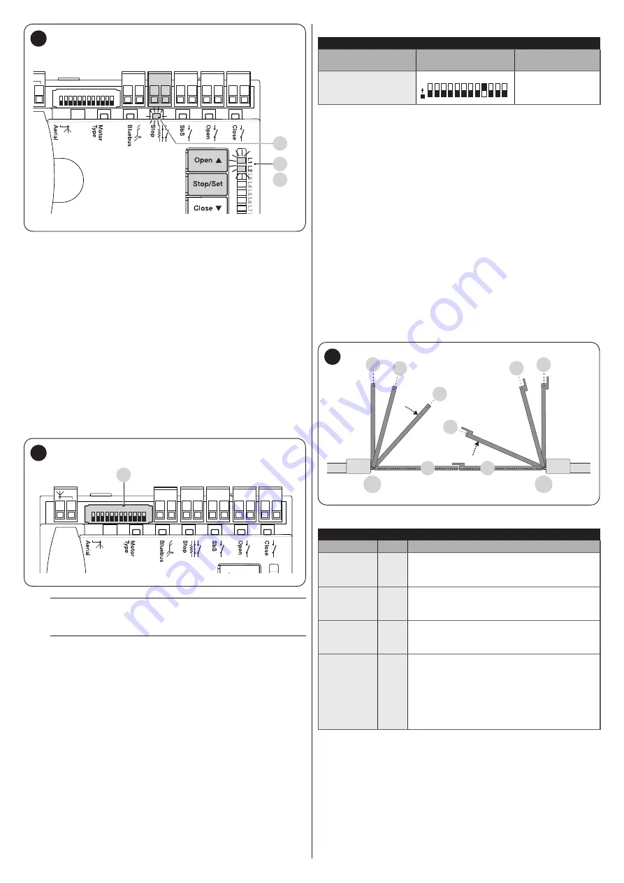
LEDs
“L1”
and
“L2”
on the control unit (“
Figure
”) emit some
slow flashes to signal that the learning stage must be carried
out.
To do this:
1.
simultaneously press and hold the
f
and
g
buttons
2.
release the buttons when LEDs
“L1”
and
“L2”
start
flashing quickly (after roughly 3 seconds)
3.
wait a few seconds until the control unit has completed the
device learning phase
4.
once this phase terminates, the
“Stop”
(
S
) LED must be lit
and LEDs
“L1”
and
“L2”
must switch off (LEDs “L3” and
“L4” could start flashing).
4.7 MOTOR SELECTOR
The control unit is equipped with a selector (
A
- “
Figure
”) that
allows for specifying which type of motor to use (see “
Close
Open
SbS
Stop
Bluebus
1 2 3 4 5 6 7 8 9 10 11 12
A
13
m
The motor selector must be set before activating
the mechanical stop learning function.
m
Any configuration not appearing in “Table 4” is not
allowed.
Table 4
SELECTING THE MOTOR TYPE
Motor type
Motor selector
Visualisation on
Oview
T05624I -
TTN3724RHS -
TTN6024RHS
1
O
N
2 3 4 5 6 7 8 9 10 11 12
TO5624I
4.8 LEARNING OF THE MECHANICAL STOP
POSITIONS
Once the connected devices have been learned, the mechanical
stop positions must be learned (maximum opening and
maximum closing). This procedure can be carried out in three
different ways:
automatic
,
manual
and
mixed
.
In
automatic
mode, the control unit learns the mechanical stops,
calculates the most appropriate gate leaf offsets and calculates
the slowdown points
“SA”
and
“SC”
(“
Figure
In the
manual
mode, the positions (“
Figure
”) are programmed
one by one, by shifting the leaves to the desired points. The
position to be programmed can be identified when one of the
eight LEDs
“L1...L8”
flashes (see “
“).
In the
mixed
mode, it is possible to perform the automatic
procedure and then, with the manual procedure, modify one or
more positions with the exception of the
“0”
and
“1”
positions,
which correspond to the mechanical stop positions.
1
1
M1
M2
0
0
SC
SA
A
A
14
Table 5
PROGRAMMING POSITIONS
Position
LED
Description
Position 0
(motor 1)
L1
maximum closing position: when the leaf
relative to motor 1 strikes the closing
mechanical stop
Position 0
(motor 2)
L2
maximum closing position: when the leaf
relative to motor 2 strikes the closing
mechanical stop
Position SA
(motor 2)
L3
Offset on opening: when the leaf associated
with motor 2 moves beyond this position,
leaf 1 will start to open
Position A
(motor 1)
L4
Desired opening position: position in which
the leaf associated with motor 1 must stop
at the end of an opening manoeuvre. This
position must not necessarily correspond
to the opening mechanical stop; it can be
chosen as desired between positions “0”
and “1”
Содержание MC824HR
Страница 1: ...Nice MC824HR Control unit EN Instructions and warnings for installation and use...
Страница 24: ...24 ENGLISH NOTES...
Страница 26: ...26 ENGLISH NOTES...
Страница 27: ...ENGLISH 27 NOTES...
Страница 28: ...www niceforyou com Nice SpA Via Callalta 1 31046 Oderzo TV Italy info niceforyou com IDV0133A01EN_15 01 2019...


