Chapter 4 - Terminals and Optional Equipment
Chapter 4
4 - 45
4.14.4
APR Adapters
- P/N 0910082
The APR Adapter provides an analog interface for the digital Enhanced keyset. The analog device can be a
single line terminal, modem, credit card, reader, wireless headset, or any other comatible analog device. It
provides ringing which allows the connected device to be used for incoming and outgoing calls. This adapter
also provides a separate extension number for the analog device, which allows both devices to be used at the
same time (this can be removed in system programming if you wish).
The adapter receives it power from the keyset. The maximum distance between the APR Adapter and the
analog terminal is 49
’
.
When installing or removing the adapters,
the keyset should first be unplugged from the system
. Terminals
with an adapter installed can be wall-mounted, however, a separate wall-mount bracket must be used (P/N
680610).
The APR Adapter does not support reverse-polarity.
For specifications, refer to
UX5000 SYSTEM SPECIFICATIONS
(page 6-1).
4.14.4.1
Installing the APR Adapter:
1.
Set the dip switches.
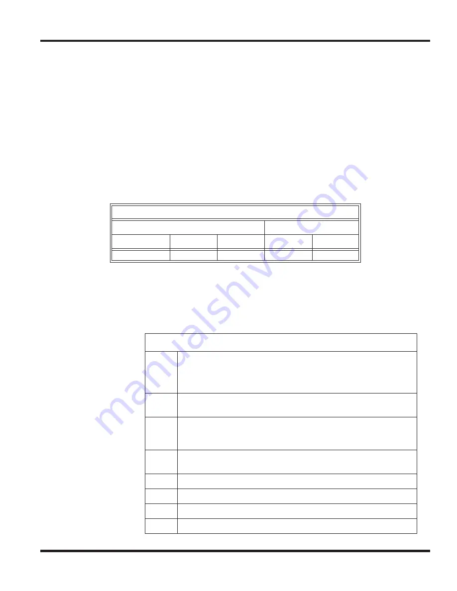
Option Compatibility
IP Terminal
Digital Keyset
IP-CTS
Enhanced
Value
Enhanced
Value
NA
NA
NA
✔
NA
APR Dip Switches
Bit 1
Retro mode - Set to On when a UX5000 keyset with an APR adapter
is used on an Aspire telephone system (then set bits 2-4). Set to Off
for a UX5000 keyset with an APR adapter is used on a UX5000
system. (bits 2-4 or disregarded).
Bit 2
With retro mode on, determine if the CPU controls the dB exchange
(On) or if the APR Bit 3 controls it (Off).
Bit 3
With retro mode on, determine if Non-0dB exchange/Hook Flash Start
Time should be used (On) or of 0dB exchange/Hook Flash Start Time
is used (Off).
Bit 4
With retro mode on, select the impedance: Off = 600ohm, On =
Complex
Bit 5
Unused
Bit 6
For firmware upgrade. Normal operation has this bit On.
Bit 7
Unused
Bit 8
Unused
Содержание UX5000
Страница 12: ...x Table of Contents Table of Contents...
Страница 18: ...1 6 Chapter 1 Chapter 1 Installing the Chassis...
Страница 26: ...1 14 Chapter 1 Chapter 1 Installing the Chassis...
Страница 80: ...1 68 Chapter 1 Chapter 1 Installing the Chassis Figure 1 90 19 CHASSIS A RACK MOUNT INSTALLATION...
Страница 84: ...1 72 Chapter 1 Chapter 1 Installing the Chassis...
Страница 90: ...2 4 Chapter 2 Chapter 2 Blade Installation and Startup...
Страница 98: ...2 12 Chapter 2 Chapter 2 Blade Installation and Startup...
Страница 113: ...Chapter 2 Blade Installation and Startup Chapter 2 2 27 Figure 2 11 EXIFU CABLING...
Страница 118: ...2 32 Chapter 2 Chapter 2 Blade Installation and Startup Figure 2 15 INTRAMAIL COMPACT FLASH CARD...
Страница 144: ...2 58 Chapter 2 Chapter 2 Blade Installation and Startup...
Страница 172: ...2 86 Chapter 2 Chapter 2 Blade Installation and Startup...
Страница 174: ...2 88 Chapter 2 Chapter 2 Blade Installation and Startup...
Страница 208: ...4 14 Chapter 4 Chapter 4 Terminals and Optional Equipment...
Страница 212: ...4 18 Chapter 4 Chapter 4 Terminals and Optional Equipment...
Страница 220: ...4 26 Chapter 4 Chapter 4 Terminals and Optional Equipment...
Страница 222: ...4 28 Chapter 4 Chapter 4 Terminals and Optional Equipment...
Страница 224: ...4 30 Chapter 4 Chapter 4 Terminals and Optional Equipment...
Страница 226: ...4 32 Chapter 4 Chapter 4 Terminals and Optional Equipment...
Страница 228: ...4 34 Chapter 4 Chapter 4 Terminals and Optional Equipment...
Страница 254: ...4 60 Chapter 4 Chapter 4 Terminals and Optional Equipment...
Страница 260: ...4 66 Chapter 4 Chapter 4 Terminals and Optional Equipment...
Страница 274: ...4 80 Chapter 4 Chapter 4 Terminals and Optional Equipment...
Страница 284: ...5 4 Chapter 5 Chapter 5 LAN Connection...
Страница 332: ...vi Index Index...


