Chapter 4 - Terminals and Optional Equipment
Chapter 4
4 - 71
4.17.5.1 Programming the Terminal’s Display Contrast
1.
With the terminal not plugged in and the handset on-hook, press the “4” and “6” buttons on the
dial pad and connect the terminal cables.
2.
This places the terminal into Service Class R/W mode. The MW LED will not be lit.
3.
Press “5” to enter the Main LCD Contrast Setting mode.
4.
Save to memory by pressing line key 2, 8, 14, or 20. The display changes back to the Service
Class R/W mode and the MW LED will be lit red.
5.
Press Exit to return the terminal to idle condition.
4.17.5.2 Programming the Terminal’s Displayed Names
1.
The names displayed on the DESI-Less terminal must be defined in system programming -
Program 15-20-01 : LCD Line Key Name Assignment.
✍
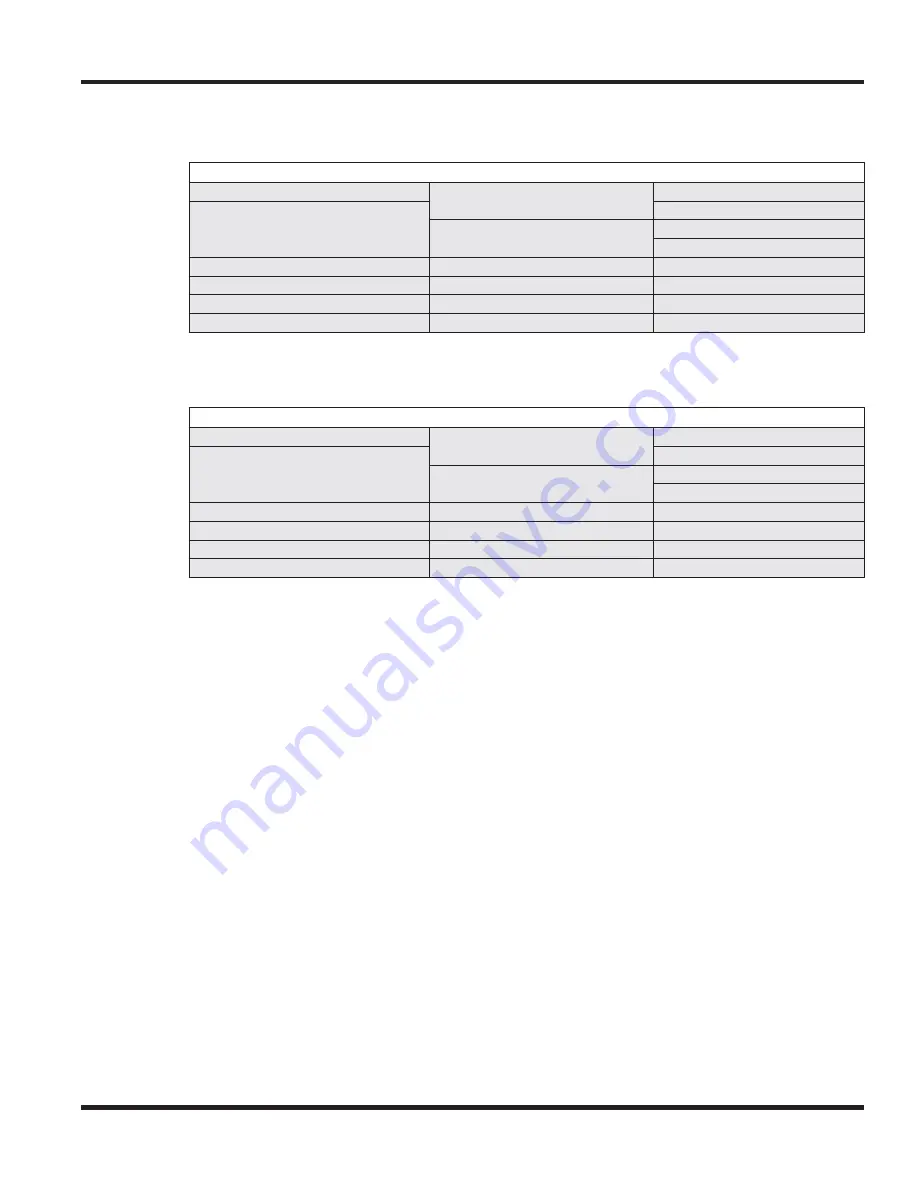
At a glance
Enhanced DESI-Less (
Digital
) Terminal
(some features require optional equipment)
Function Keys:
✔
Digital DESI-Less Line
Key/LCD Unit:
No
60-Button DSS Console:
✔
Handsfree (Speakerphone):
ADA Adapter:
✔
Full Duplex
✔
IP DESI-Less Line Key/
LCD Unit:
No
APR Adapter:
✔
Half Duplex
-
BCH Adapter:
✔
Dual LEDs:
✔
12 Line Key Kit:
✔
BHA Adapter:
✔
Backlit LCD:
✔
16-Button DLS
✔
PSA Adapter:
✔
Backlit Display
✔
Headset Jack:
✔
Retro Dial Pad:
✔
Soft Keys:
✔
Lock Button:
No
Navigator Pad
✔
✍
At a glance
Enhanced DESI-Less (
IP
) Terminal
(some features require optional equipment)
Function Keys:
✔
Digital DESI-Less Line
Key/LCD Unit:
No
60-Button DSS Console:
✔
Handsfree (Speakerphone):
ADA Adapter:
✔
Full Duplex
✔
IP DESI-Less Line Key/
LCD Unit:
No
APR Adapter:
No
Half Duplex
-
BCH Adapter:
No
Dual LEDs:
✔
12 Line Key Kit:
✔
BHA Adapter:
No
Backlit LCD:
✔
16-Button DLS
✔
PSA Adapter:
✔
Backlit Display
✔
Headset Jack:
✔
Retro Dial Pad:
✔
Soft Keys:
✔
Lock Button:
✔
Navigator Pad
✔
Содержание UX5000
Страница 12: ...x Table of Contents Table of Contents...
Страница 18: ...1 6 Chapter 1 Chapter 1 Installing the Chassis...
Страница 26: ...1 14 Chapter 1 Chapter 1 Installing the Chassis...
Страница 80: ...1 68 Chapter 1 Chapter 1 Installing the Chassis Figure 1 90 19 CHASSIS A RACK MOUNT INSTALLATION...
Страница 84: ...1 72 Chapter 1 Chapter 1 Installing the Chassis...
Страница 90: ...2 4 Chapter 2 Chapter 2 Blade Installation and Startup...
Страница 98: ...2 12 Chapter 2 Chapter 2 Blade Installation and Startup...
Страница 113: ...Chapter 2 Blade Installation and Startup Chapter 2 2 27 Figure 2 11 EXIFU CABLING...
Страница 118: ...2 32 Chapter 2 Chapter 2 Blade Installation and Startup Figure 2 15 INTRAMAIL COMPACT FLASH CARD...
Страница 144: ...2 58 Chapter 2 Chapter 2 Blade Installation and Startup...
Страница 172: ...2 86 Chapter 2 Chapter 2 Blade Installation and Startup...
Страница 174: ...2 88 Chapter 2 Chapter 2 Blade Installation and Startup...
Страница 208: ...4 14 Chapter 4 Chapter 4 Terminals and Optional Equipment...
Страница 212: ...4 18 Chapter 4 Chapter 4 Terminals and Optional Equipment...
Страница 220: ...4 26 Chapter 4 Chapter 4 Terminals and Optional Equipment...
Страница 222: ...4 28 Chapter 4 Chapter 4 Terminals and Optional Equipment...
Страница 224: ...4 30 Chapter 4 Chapter 4 Terminals and Optional Equipment...
Страница 226: ...4 32 Chapter 4 Chapter 4 Terminals and Optional Equipment...
Страница 228: ...4 34 Chapter 4 Chapter 4 Terminals and Optional Equipment...
Страница 254: ...4 60 Chapter 4 Chapter 4 Terminals and Optional Equipment...
Страница 260: ...4 66 Chapter 4 Chapter 4 Terminals and Optional Equipment...
Страница 274: ...4 80 Chapter 4 Chapter 4 Terminals and Optional Equipment...
Страница 284: ...5 4 Chapter 5 Chapter 5 LAN Connection...
Страница 332: ...vi Index Index...


