


Chapter 3: 7401-2xxx and 3xxx Hardware Installation
3-41
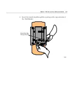
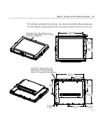
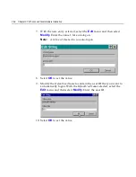
The following illustration shows the maximum allowable dimensions
for the display opening when the optional cosmetic bezel is not used.
19101
312.5 mm
12.305 in.
13.7 mm
0.540 in.
235.6 mm
9.275 in.
27.5 mm
1.083 in.
22.9 mm
0.900 in.
17.2 mm
0.678 in.
Gasket must meet inside surface of custom
application's display opening. This is to provide
a secure and watertight fit.
Use four #8-32 machine screws in the
corners of the unit to mount the display
into an enclosure. Six total screws may
be used for multiple mounting configurations.
345.4 mm
13.6 in.
156.2 mm
6.15 in.
292.4 mm
11.51 in.
141.6 mm
5.575 in.
175 mm
6.888 in.
200.7 mm
7.9 in.
Содержание EasyPoint 7401
Страница 1: ...NCR EasyPoint 7401 Release 2 5 Hardware User s Guide 19797 NCR B005 0000 1254 Issue H...
Страница 18: ...xvi...
Страница 24: ...xxii...
Страница 98: ......
Страница 117: ...Chapter 3 7401 2xxx and 3xxx Hardware Installation 3 19 2 Remove the Core Module from the Fixed Angle Mount 16397...
Страница 156: ......
Страница 188: ...4 32 Chapter 4 7401 4xxx Hardware Installation...
Страница 220: ...5 32 Chapter 5 Setup...
Страница 260: ...7 10 Chapter 7 BIOS Updating Procedures...
Страница 266: ...8 6 Chapter 8 NCR 7401 7890 or 7892 Scanner Differences...
Страница 279: ......
Страница 280: ...B005 0000 1254 Dec 2002 Printed on recycled paper...


