


NX50 Troubleshooting Manual
Responding to alarms
Page 1-34
Issue 6.0 2019-04-01
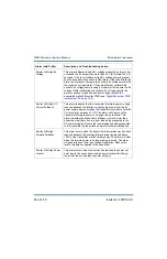
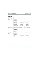
Rack #: Power Module #
Not Responding
This alarm indicates that the rack interface PWB is not receiving a
response from the associated RF power module. Try swapping
the affected RF power module with an RF power module in
another location. If the alarm follows the RF power module,
replace the RF power module
Rack #: Rectifier Fan 1
(or 2) Fail
This alarm occurs if the speed of one of the SCR rectifier’s cooling
fans is below 3000 RPM for longer than 15 seconds. Inspect the
affected fan and, if necessary, replace it (see
Inspection/Replacement” on page 1-80
Rack #: +15 V Fail
This alarm occurs if the +15 V rail is outside the acceptable range
(12 V to 18 V). Disconnect the DC output of both +15 V power
supplies, and measure the voltage of each. If the output voltage of
either power supply measures outside of the acceptable range,
replace the affected power supply. If both power supplies measure
within the acceptable range, replace the rack interface PWB (see
“Rack Interface PWB replacement” on page 1-76
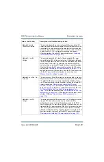
Rack #: +15 V A (or B)
Fail
The digital fault reporting output of 15 V power supply (U3
or U4) is active. If the o15 V Fail alarm is active, follow the
troubleshooting steps for that alarm. Otherwise, check continuity
of the cabling between the asso15 V power supply and
the rack interface PWB. If the cabling looks OK, and all
connections are tight, replace the asso15 V power supply
(see
“Low Voltage Power Supply Replacement” on page 1-81
Rack #: -15 V Fail
This alarm occurs if the -15 V rail is outside its acceptable range of
-12 to -18 V. Suspect a faulty dc-dc converter on the rack interface
PWB. Replace the rack interface PWB (see
).
Rack #: -15 V A (or B)
Fail
This alarm occurs if the associated
-15 V power supply’s output
voltage is outside its acceptable range of -12 to -18 V. Suspect a
faulty dc-dc converter on the rack interface PWB. Replace the
rack interface PWB (see
“Rack Interface PWB replacement” on
Rack #: +30 V Fail
This alarm occurs if the +30 V rail has varied outside its
acceptable range of 25 to 35 V. Suspect a faulty dc-dc converter
on the rack interface PWB. Replace the rack interface PWB (see
“Rack Interface PWB replacement” on page 1-76
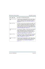
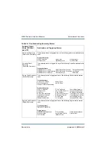
Alarm (with Prefix)
Description and Troubleshooting Action
Содержание NX50
Страница 1: ...NX50 Transmitter Troubleshooting Manual Document NHB NX50 TRB Issue 6 0 2019 04 01 Status Standard...
Страница 2: ......
Страница 4: ......
Страница 8: ...NX50 Troubleshooting Manual Page viii Issue 6 0 2019 04 01...
Страница 10: ...NX50 Troubleshooting Manual Page x Issue 6 0 2019 04 01...
Страница 108: ...NX50 Troubleshooting Manual Responding to alarms Page 1 98 Issue 6 0 2019 04 01...
Страница 153: ...NX50 Troubleshooting Manual Reading Electrical Schematics Page 4 6 Issue 6 0 2019 04 01...
Страница 184: ...Issue 6 0 2019 04 01 MD 4 Figure MD 4 NAPI95A 01 Power Module Interface PWB...
Страница 188: ...Issue 6 0 2019 04 01 MD 8 Figure MD 8 NAPI106 Remote Interface PWB...
Страница 192: ...Issue 6 0 2019 04 01 MD 12 Figure MD 12 NAPI98 RF Drive Distribution PWB...
Страница 194: ...Issue 6 0 2019 04 01 MD 14 Figure MD 14 NAX243B 01 B Distribution Assembly J1 R1 R2 R3 R4 Front View Rear View...
Страница 198: ...Issue 6 0 2019 04 01 MD 18 Figure MD 18 Fan Tray Assembly 207 8133 B1 B2 J1 AIR FLOW AIR FLOW...
Страница 200: ...Issue 6 0 2019 04 01 MD 20 Figure MD 20 Current Probe 207 6213 10 Front View Rear View T1 R1 R2 R3 R4 J1 P1...
Страница 201: ...Issue 6 0 2019 04 01 MD 21 Figure MD 21 NAFP106B 01 Directional Coupler A1 DETAIL...
Страница 204: ......


