NX50 Troubleshooting Manual
Responding to alarms
Page 1-10
Issue 6.0 2019-04-01
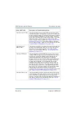
Controller: EEPROM
Failure: Thresholds
This alarm occurs when the transmitter is unable to read its
configuration for transmitter type and rack interface serial
numbers from EEPROM upon boot-up. The transmitter will revert
to its initial default settings, which may be different from the values
set before the transmitter was shipped. The alarm will remain
asserted until the setting is changed. Change the transmitter type
to the correct setting.
Remove and re-apply the ac power to the
transmitter. If the alarm persists, replace the battery on the
control/interface PWB and retry the above steps. If the alarm
persists, replace the control/interface PWB (see
Controller: EEPROM
Failure: Potentiometers
This alarm occurs when the transmitter is unable to read its RF
Symmetry Adjustment calibration from EEPROM upon boot-up.
The alarm will remain asserted until the RF Symmetry has been
re-calibrated. When this alarm occurs, the transmitter will load a
default level of exactly mid-scale for the symmetry adjustment
potentiometers. Set the RF Symmetry Adjust per the factory
configuration. Cycle (turn off, then on) ac power to the transmitter.
If the alarm persists, replace the battery on the control/interface
PWB and retry the above steps. If the alarm persists, replace the
control/interface PWB (see
“Control/interface PWB replacement”
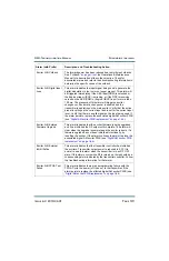
Controller: EEPROM
Failure: Remotes
This alarm occurs when the transmitter is unable to read its
remote I/O configuration from EEPROM upon boot-up. The
transmitter will revert to the initial default remote I/O settings and
the alarm will remain asserted until a new remote input/output is
configured. Reconfigure the remote I/O settings as desired. Cycle
(turn off, then on) ac power to the transmitter. If the alarm persists,
replace the battery on the control/interface PWB and re-try the
above steps. If the alarm persists, replace the control/interface
PWB
“Control/interface PWB replacement” on page 1-64
).
Controller: EEPROM
Failure: Schedule
This alarm occurs when the transmitter is unable to read its
schedule configuration from EEPROM upon boot-up. The
transmitter will establish a new, completely blank schedule. The
alarm will remain asserted until at least one new scheduled event
is created. Recreate the desired schedule settings. Cycle (turn off,
then on) ac power to the transmitter. If the alarm persists, replace
the battery on the control/interface PWB and retry the above
steps. If it still persists, replace the control/interface PWB (see
“Control/interface PWB replacement” on page 1-64
Alarm (with Prefix)
Description and Troubleshooting Action
Содержание NX50
Страница 1: ...NX50 Transmitter Troubleshooting Manual Document NHB NX50 TRB Issue 6 0 2019 04 01 Status Standard...
Страница 2: ......
Страница 4: ......
Страница 8: ...NX50 Troubleshooting Manual Page viii Issue 6 0 2019 04 01...
Страница 10: ...NX50 Troubleshooting Manual Page x Issue 6 0 2019 04 01...
Страница 108: ...NX50 Troubleshooting Manual Responding to alarms Page 1 98 Issue 6 0 2019 04 01...
Страница 153: ...NX50 Troubleshooting Manual Reading Electrical Schematics Page 4 6 Issue 6 0 2019 04 01...
Страница 184: ...Issue 6 0 2019 04 01 MD 4 Figure MD 4 NAPI95A 01 Power Module Interface PWB...
Страница 188: ...Issue 6 0 2019 04 01 MD 8 Figure MD 8 NAPI106 Remote Interface PWB...
Страница 192: ...Issue 6 0 2019 04 01 MD 12 Figure MD 12 NAPI98 RF Drive Distribution PWB...
Страница 194: ...Issue 6 0 2019 04 01 MD 14 Figure MD 14 NAX243B 01 B Distribution Assembly J1 R1 R2 R3 R4 Front View Rear View...
Страница 198: ...Issue 6 0 2019 04 01 MD 18 Figure MD 18 Fan Tray Assembly 207 8133 B1 B2 J1 AIR FLOW AIR FLOW...
Страница 200: ...Issue 6 0 2019 04 01 MD 20 Figure MD 20 Current Probe 207 6213 10 Front View Rear View T1 R1 R2 R3 R4 J1 P1...
Страница 201: ...Issue 6 0 2019 04 01 MD 21 Figure MD 21 NAFP106B 01 Directional Coupler A1 DETAIL...
Страница 204: ......


