


NX50 Troubleshooting Manual
Responding to alarms
Issue 6.0 2019-04-01
Page 1-91
1. Set the transmitter to its RF Off state and turn off (disable) the ac power at the source.
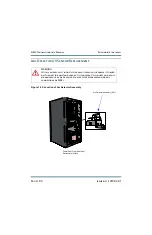
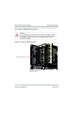
Lift the air filter (slide it up) to verify the LEDs on the power module interface PWBs
are off (green when on), indicating the B+ capacitors are discharged. Open the rear
door of the cabinet and verify the six ac indicator LEDs on the rectifier assembly are
off (amber when on). For additional safety, measure the dc voltage across the + and -
terminals of any of the large, electrolytic capacitors on the floor of the cabinet as well
as the line-to-line and line-to-ground voltages at the ac input terminals. There should be
little or no ac or dc voltage. DO NOT PROCEED if either the ac or dc voltage is
greater than 5 V.
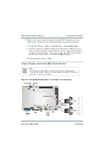
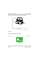
2. Disconnect the cable attached to the arc detector assembly (see
), taking note of the connector label on the cable and the assembly.
3. Carefully remove and retain the two (2) sets of mounting hardware and remove the arc
detector assembly from the transmitter chassis. Remove the UV sensor (U2) from the
arc detector assembly’s driver PWB (U1) through the hole on top of the enclosure (see
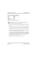
4. Obtain a replacement UV sensor (Nautel Part # UB89).
5. Cut the anode lead of the UV sensor to the same length as the cathode, noting the
anode/cathode orientation and taking care not to bend the leads. Install the UV sensor
on the arc detector assembly’s driver PWB (U1), ensuring proper orientation (see
).
6. Complete the replacement procedure by reversing
.
7. Close the rear door and turn on (enable) the ac power source to resume transmitter
operation. Ensure the offending alarm has cleared.
WARNING:
Take special care when handling the UV sensor after removing it from
the packaging so it does not receive impact shock. Do not allow skin
contact with the glass face. Wear clean gloves to ensure no oils from
your skin contact the surface of the glass.
Содержание NX50
Страница 1: ...NX50 Transmitter Troubleshooting Manual Document NHB NX50 TRB Issue 6 0 2019 04 01 Status Standard...
Страница 2: ......
Страница 4: ......
Страница 8: ...NX50 Troubleshooting Manual Page viii Issue 6 0 2019 04 01...
Страница 10: ...NX50 Troubleshooting Manual Page x Issue 6 0 2019 04 01...
Страница 108: ...NX50 Troubleshooting Manual Responding to alarms Page 1 98 Issue 6 0 2019 04 01...
Страница 153: ...NX50 Troubleshooting Manual Reading Electrical Schematics Page 4 6 Issue 6 0 2019 04 01...
Страница 184: ...Issue 6 0 2019 04 01 MD 4 Figure MD 4 NAPI95A 01 Power Module Interface PWB...
Страница 188: ...Issue 6 0 2019 04 01 MD 8 Figure MD 8 NAPI106 Remote Interface PWB...
Страница 192: ...Issue 6 0 2019 04 01 MD 12 Figure MD 12 NAPI98 RF Drive Distribution PWB...
Страница 194: ...Issue 6 0 2019 04 01 MD 14 Figure MD 14 NAX243B 01 B Distribution Assembly J1 R1 R2 R3 R4 Front View Rear View...
Страница 198: ...Issue 6 0 2019 04 01 MD 18 Figure MD 18 Fan Tray Assembly 207 8133 B1 B2 J1 AIR FLOW AIR FLOW...
Страница 200: ...Issue 6 0 2019 04 01 MD 20 Figure MD 20 Current Probe 207 6213 10 Front View Rear View T1 R1 R2 R3 R4 J1 P1...
Страница 201: ...Issue 6 0 2019 04 01 MD 21 Figure MD 21 NAFP106B 01 Directional Coupler A1 DETAIL...
Страница 204: ......


