


NX50 Troubleshooting Manual
Responding to alarms
Issue 6.0 2019-04-01
Page 1-11
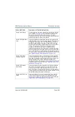
Controller: Exciter A (or
B) Not Responding
This alarm occurs when the controller is configured to expect
exciter A (or B) is installed, and it has failed to receive any serial
response from that exciter. The alarm is cleared if the controller is
configured to expect that same exciter is not installed, or if it
receives a serial response from the exciter. When this alarm
occurs on the standby exciter, automatic changeover will be
inhibited. When this alarm occurs on the main exciter, if automatic
changeovers are enabled and the main exciter is active and the
standby exciter is responding to serial communication, an
automatic changeover will occur. If there are two exciters in the
transmitter, swap exciter positions. If the alarm follows the exciter,
or there is only one exciter in the system, replace the digital AM
exciter PWB (see
“Digital AM exciter PWB replacement” on
). If the alarm persists, or the alarm remains with the
position, replace the control/interface PWB (see
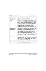
Controller: Exciter
Changeover
This alarm indicates that an automatic exciter changeover has
occurred. This alarm will occur as a result of another alarm
triggering the automatic exciter changeover. Follow the
troubleshooting information for the associated alarm.
Controller: Exgine Not
Responding
This alarm indicates the transmitter is configured for an IBOC
mode of operation and the controller has not received any
communication from the Exgine over a set period of time. The
alarm will clear if the transmitter is configured for a non-IBOC
mode of operation, or the controller receives a response from the
Exgine. If the Exgine is operating normally, ignore this alarm. If the
Exgine is not operating normally, cycle ac power to the transmitter.
If the alarm persists, inspect the cabling between the Exgine and
the transmitter controller. If the cabling is acceptable and the
alarm persists, replace the Exgine PWB
). If the alarm persists, or the alarm
remains with the position, replace the control/interface PWB (see
“Control/interface PWB replacement” on page 1-64
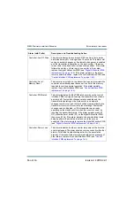
Alarm (with Prefix)
Description and Troubleshooting Action
Содержание NX50
Страница 1: ...NX50 Transmitter Troubleshooting Manual Document NHB NX50 TRB Issue 6 0 2019 04 01 Status Standard...
Страница 2: ......
Страница 4: ......
Страница 8: ...NX50 Troubleshooting Manual Page viii Issue 6 0 2019 04 01...
Страница 10: ...NX50 Troubleshooting Manual Page x Issue 6 0 2019 04 01...
Страница 108: ...NX50 Troubleshooting Manual Responding to alarms Page 1 98 Issue 6 0 2019 04 01...
Страница 153: ...NX50 Troubleshooting Manual Reading Electrical Schematics Page 4 6 Issue 6 0 2019 04 01...
Страница 184: ...Issue 6 0 2019 04 01 MD 4 Figure MD 4 NAPI95A 01 Power Module Interface PWB...
Страница 188: ...Issue 6 0 2019 04 01 MD 8 Figure MD 8 NAPI106 Remote Interface PWB...
Страница 192: ...Issue 6 0 2019 04 01 MD 12 Figure MD 12 NAPI98 RF Drive Distribution PWB...
Страница 194: ...Issue 6 0 2019 04 01 MD 14 Figure MD 14 NAX243B 01 B Distribution Assembly J1 R1 R2 R3 R4 Front View Rear View...
Страница 198: ...Issue 6 0 2019 04 01 MD 18 Figure MD 18 Fan Tray Assembly 207 8133 B1 B2 J1 AIR FLOW AIR FLOW...
Страница 200: ...Issue 6 0 2019 04 01 MD 20 Figure MD 20 Current Probe 207 6213 10 Front View Rear View T1 R1 R2 R3 R4 J1 P1...
Страница 201: ...Issue 6 0 2019 04 01 MD 21 Figure MD 21 NAFP106B 01 Directional Coupler A1 DETAIL...
Страница 204: ......