


NX50 Troubleshooting Manual
Responding to alarms
Issue 6.0 2019-04-01
Page 1-47
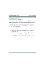
RF power module fault validation
Each RF power module has a multi-colour LED on its front panel, which can help in
identifying a fault and allowing you to determine whether remedial action is required now or
later.
Identify and isolate a defective RF power module, and verify the nature of the defect by
checking the LEDs on the RF power modules’ front panels. Note which RF power module is
not operating normally and producing RF power (i.e., LED is not solid green). Record which
RF power modules are displaying an alarm and the state of its LED (see below).
– solid green: module is producing RF with no alarms
– flashing amber and off: module is RF off
– solid red: module has a non-latching alarm, and is not producing RF
– flashing red, then green: module is producing RF, but has an alarm
– long red, short amber: module has a latching alarm, and is not producing RF
– long red, short off: module has no valid serial number
– short red, long off: module has no valid serial address on the internal bus
– long amber, short green: module is producing RF, but is receiving no serial
communication from the rack interface
– long amber, short red: module is not producing RF and is receiving no serial
communication from the rack interface
Except in the case of a
High DC Current
,
High PA Voltage
and
Residual PA Voltage
alarm,
attempt to reset an RF power module by disconnecting and reconnecting the RJ45 plug in the
front of the module. If you cannot reset the front panel LED alarm, see
RF power module troubleshooting
“Removing and reinstalling RF power modules” on page 1-51
for removal and
installation instructions and then refer to
“Troubleshooting RF power modules” on page 1-56
for detailed troubleshooting information.
NOTE:
A defective RF power module can be removed for repair, without turning off the
transmitter, as described in
“Removing an RF power module” on page 1-51
. The
transmitter can be operated at a reduced output power level with an RF power
module removed.
Содержание NX50
Страница 1: ...NX50 Transmitter Troubleshooting Manual Document NHB NX50 TRB Issue 6 0 2019 04 01 Status Standard...
Страница 2: ......
Страница 4: ......
Страница 8: ...NX50 Troubleshooting Manual Page viii Issue 6 0 2019 04 01...
Страница 10: ...NX50 Troubleshooting Manual Page x Issue 6 0 2019 04 01...
Страница 108: ...NX50 Troubleshooting Manual Responding to alarms Page 1 98 Issue 6 0 2019 04 01...
Страница 153: ...NX50 Troubleshooting Manual Reading Electrical Schematics Page 4 6 Issue 6 0 2019 04 01...
Страница 184: ...Issue 6 0 2019 04 01 MD 4 Figure MD 4 NAPI95A 01 Power Module Interface PWB...
Страница 188: ...Issue 6 0 2019 04 01 MD 8 Figure MD 8 NAPI106 Remote Interface PWB...
Страница 192: ...Issue 6 0 2019 04 01 MD 12 Figure MD 12 NAPI98 RF Drive Distribution PWB...
Страница 194: ...Issue 6 0 2019 04 01 MD 14 Figure MD 14 NAX243B 01 B Distribution Assembly J1 R1 R2 R3 R4 Front View Rear View...
Страница 198: ...Issue 6 0 2019 04 01 MD 18 Figure MD 18 Fan Tray Assembly 207 8133 B1 B2 J1 AIR FLOW AIR FLOW...
Страница 200: ...Issue 6 0 2019 04 01 MD 20 Figure MD 20 Current Probe 207 6213 10 Front View Rear View T1 R1 R2 R3 R4 J1 P1...
Страница 201: ...Issue 6 0 2019 04 01 MD 21 Figure MD 21 NAFP106B 01 Directional Coupler A1 DETAIL...
Страница 204: ......


