


NX50 Troubleshooting Manual
Responding to alarms
Page 1-30
Issue 6.0 2019-04-01
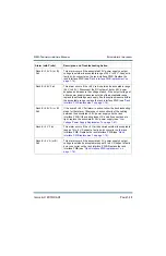
Module #: Low RF Drive
This alarm indicates the RF drive duty cycle of the affected RF
power module is below 35%. The affected RF power module is
immediately disabled. Try swapping the affected RF power
module with an operational RF power module in another position.
If the fault follows the RF power module, replace the RF power
module (see
“Removing and reinstalling RF power modules” on
). If the fault remains with that position, and is also
present on n adjacent power module, try replacing the associated
RF Drive cable. If the alarm persists, replace the RF Drive
Distribution PWB (see
“RF drive distribution PWB replacement”
.
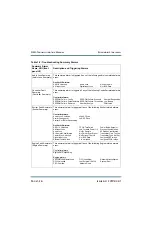
Module #: No Controller
Communications
This alarm indicates the RF power module has not received any
communication from the rack interface for 10 seconds. Try
swapping the affected RF power module with an operational RF
power module in another position. If the alarm follows the RF
power module, replace the RF power module
reinstalling RF power modules” on page 1-51
). If the alarm
remains with the position, replace the rack interface PWB
(see
“Rack Interface PWB replacement” on page 1-76
Module #:
Overmodulation
This alarm indicates the RF power module's PDM Duty Cycle
meter is above 95%. Verify the modulation being applied to the
transmitter is not too high. Try swapping the RF power module
with an RF power module that is not showing this alarm. If the
alarm follows the RF power module, replace the RF power module
(see
“Removing and reinstalling RF power modules” on page 1-
). If the alarm remains with the original position, try replacing
the digital AM exciter PWB
(see
) or the control/interface PWB
(see
“Control/interface PWB replacement” on page 1-64
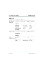
Module #: Residual PA
Voltage
Present
This alarm indicates the PA voltage of the RF power module is
higher than expected with either the modulator or the RF amplifier
disabled. See
“Troubleshooting RF power modules” on page 1-56
to determine whether to replace the affected RF power module or
to repair damaged parts, suspecting a failure of one of the FETs.
Alarm (with Prefix)
Description and Troubleshooting Action
Содержание NX50
Страница 1: ...NX50 Transmitter Troubleshooting Manual Document NHB NX50 TRB Issue 6 0 2019 04 01 Status Standard...
Страница 2: ......
Страница 4: ......
Страница 8: ...NX50 Troubleshooting Manual Page viii Issue 6 0 2019 04 01...
Страница 10: ...NX50 Troubleshooting Manual Page x Issue 6 0 2019 04 01...
Страница 108: ...NX50 Troubleshooting Manual Responding to alarms Page 1 98 Issue 6 0 2019 04 01...
Страница 153: ...NX50 Troubleshooting Manual Reading Electrical Schematics Page 4 6 Issue 6 0 2019 04 01...
Страница 184: ...Issue 6 0 2019 04 01 MD 4 Figure MD 4 NAPI95A 01 Power Module Interface PWB...
Страница 188: ...Issue 6 0 2019 04 01 MD 8 Figure MD 8 NAPI106 Remote Interface PWB...
Страница 192: ...Issue 6 0 2019 04 01 MD 12 Figure MD 12 NAPI98 RF Drive Distribution PWB...
Страница 194: ...Issue 6 0 2019 04 01 MD 14 Figure MD 14 NAX243B 01 B Distribution Assembly J1 R1 R2 R3 R4 Front View Rear View...
Страница 198: ...Issue 6 0 2019 04 01 MD 18 Figure MD 18 Fan Tray Assembly 207 8133 B1 B2 J1 AIR FLOW AIR FLOW...
Страница 200: ...Issue 6 0 2019 04 01 MD 20 Figure MD 20 Current Probe 207 6213 10 Front View Rear View T1 R1 R2 R3 R4 J1 P1...
Страница 201: ...Issue 6 0 2019 04 01 MD 21 Figure MD 21 NAFP106B 01 Directional Coupler A1 DETAIL...
Страница 204: ......


