


NX50 Troubleshooting Manual
Responding to alarms
Page 1-22
Issue 6.0 2019-04-01
Exciter A/B: No B+
Sample
This alarm indicates the exciter’s B+ voltage sample is below 40 V
for more than 10 seconds. If there is an associated Low B+
voltage alarm, follow the troubleshooting information for that
alarm. If there are no additional alarms and there is a second
exciter installed, switch exciters and check if the alarm is present
on the other exciter. If the alarm is present on the second exciter,
check the cabling between the B+ sampling point and the control/
interface PWB. If the connection is OK, replace the control/
interface PWB (see
“Control/interface PWB replacement” on
). If the alarm is not present on the second exciter, or
there is no second exciter in the transmitter, replace the digital AM
exciter PWB (see
“Digital AM exciter PWB replacement” on
Exciter A/B: No Carrier
Sync Signal Present
This alarm will occur when the transmitter’s Sync Source is set to
GPS Sync Card or Combiner and the 10 MHz or 1 kHz
synchronization signal is either not present or out of specification.
If the Sync Source is
set to Combiner, this alarm will cause the
transmitter to be
inhibited, otherwise this alarm is displayed for
information only.
If the transmitter’s Sync Source is set to GPS
Sync Card, check the connection between the GPS sync PWB
and the control/interface PWB. If the connection is OK, replace
the GPS sync PWB
(see
If the alarm persists, replace the associated digital AM
exciter PWB
(see
“Digital AM exciter PWB replacement” on
) or the control/interface PWB (see
). If the transmitter’s Sync
Source is set to Combiner, check the connection between the
combiner and the control/interface PWB. If the connection looks
OK, troubleshoot the combiner’s synchronization signal source.
Exciter A/B: No External
10 MHz
This alarm indicates the transmitter is set to run on an external 10
MHz source, but the exciter has determined the frequency of the
external source to be outside of the range 9.9 MHz to 10.1 MHz.
This will cause the exciter to revert to using its internal 10 MHz
reference until it determines the external 10 MHz is in range. This
may also cause an exciter changeover if a backup exciter is
installed and automatic changeover is enabled. Check the
integrity and signal level of the external 10 MHz source. If the
external source is acceptable and the alarm persists, replace the
associated digital AM exciter PWB (see
).
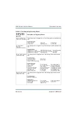
Alarm (with Prefix)
Description and Troubleshooting Action
Содержание NX50
Страница 1: ...NX50 Transmitter Troubleshooting Manual Document NHB NX50 TRB Issue 6 0 2019 04 01 Status Standard...
Страница 2: ......
Страница 4: ......
Страница 8: ...NX50 Troubleshooting Manual Page viii Issue 6 0 2019 04 01...
Страница 10: ...NX50 Troubleshooting Manual Page x Issue 6 0 2019 04 01...
Страница 108: ...NX50 Troubleshooting Manual Responding to alarms Page 1 98 Issue 6 0 2019 04 01...
Страница 153: ...NX50 Troubleshooting Manual Reading Electrical Schematics Page 4 6 Issue 6 0 2019 04 01...
Страница 184: ...Issue 6 0 2019 04 01 MD 4 Figure MD 4 NAPI95A 01 Power Module Interface PWB...
Страница 188: ...Issue 6 0 2019 04 01 MD 8 Figure MD 8 NAPI106 Remote Interface PWB...
Страница 192: ...Issue 6 0 2019 04 01 MD 12 Figure MD 12 NAPI98 RF Drive Distribution PWB...
Страница 194: ...Issue 6 0 2019 04 01 MD 14 Figure MD 14 NAX243B 01 B Distribution Assembly J1 R1 R2 R3 R4 Front View Rear View...
Страница 198: ...Issue 6 0 2019 04 01 MD 18 Figure MD 18 Fan Tray Assembly 207 8133 B1 B2 J1 AIR FLOW AIR FLOW...
Страница 200: ...Issue 6 0 2019 04 01 MD 20 Figure MD 20 Current Probe 207 6213 10 Front View Rear View T1 R1 R2 R3 R4 J1 P1...
Страница 201: ...Issue 6 0 2019 04 01 MD 21 Figure MD 21 NAFP106B 01 Directional Coupler A1 DETAIL...
Страница 204: ......