


NX50 Troubleshooting Manual
Reading Electrical Schematics
Page 4-2
Issue 6.0 2019-04-01
Unique symbols
Nautel uses unique symbols on electrical schematics to describe logic (two-state) signals. These
signals differ from single-state signals or analog signals that may have multiple values.
Type of inputs and outputs
On electrical schematics, names used to describe logic (two-state) input and output signals are
prefixed with a
#
symbol.
Logic level convention
The
#
prefix identifies an input or output signal that has two distinct states:
high
and
low
.
The suffix on an input or output signal name identifies the
active
(true) state of the signal. The
high suffix
(+) indicates the more positive of the two levels used to represent the logic states.
The
low suffix
(-) indicates the less positive of the two levels.
Two types of logic, positive and negative, may be represented on a particular schematic. In
positive logic,
high
represents the
active
(true) state, and
low
represents the
inactive
(false) state.
In negative logic,
low
represents the
active
(true) state, and
high
represents the
inactive
(false)
state.
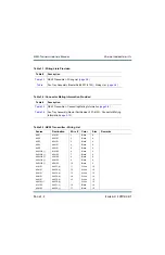
Identifying schematic diagrams
Each electrical schematic in this section is identified by a number that is both the figure
number and the page number. The numbers are assigned sequentially are prefixed by the letters
SD
. The electrical schematics and logic diagrams included in this section are listed in
Содержание NX50
Страница 1: ...NX50 Transmitter Troubleshooting Manual Document NHB NX50 TRB Issue 6 0 2019 04 01 Status Standard...
Страница 2: ......
Страница 4: ......
Страница 8: ...NX50 Troubleshooting Manual Page viii Issue 6 0 2019 04 01...
Страница 10: ...NX50 Troubleshooting Manual Page x Issue 6 0 2019 04 01...
Страница 108: ...NX50 Troubleshooting Manual Responding to alarms Page 1 98 Issue 6 0 2019 04 01...
Страница 153: ...NX50 Troubleshooting Manual Reading Electrical Schematics Page 4 6 Issue 6 0 2019 04 01...
Страница 184: ...Issue 6 0 2019 04 01 MD 4 Figure MD 4 NAPI95A 01 Power Module Interface PWB...
Страница 188: ...Issue 6 0 2019 04 01 MD 8 Figure MD 8 NAPI106 Remote Interface PWB...
Страница 192: ...Issue 6 0 2019 04 01 MD 12 Figure MD 12 NAPI98 RF Drive Distribution PWB...
Страница 194: ...Issue 6 0 2019 04 01 MD 14 Figure MD 14 NAX243B 01 B Distribution Assembly J1 R1 R2 R3 R4 Front View Rear View...
Страница 198: ...Issue 6 0 2019 04 01 MD 18 Figure MD 18 Fan Tray Assembly 207 8133 B1 B2 J1 AIR FLOW AIR FLOW...
Страница 200: ...Issue 6 0 2019 04 01 MD 20 Figure MD 20 Current Probe 207 6213 10 Front View Rear View T1 R1 R2 R3 R4 J1 P1...
Страница 201: ...Issue 6 0 2019 04 01 MD 21 Figure MD 21 NAFP106B 01 Directional Coupler A1 DETAIL...
Страница 204: ......


