


NX50 Troubleshooting Manual
Responding to alarms
Page 1-6
Issue 6.0 2019-04-01
Click the
Status
button to view the Transmitter Status page
(
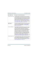
displays a list of active alarms. Alarms are listed by their origin (Device column), then by name
(Alarm column), and then by severity (Level column).
1. The Device column displays the sub-system origin of the alarm. The sub-systems that
can be displayed are:
• Controller: All Alarms in this sub-system apply to the controller.
• Exciter A or B: All Alarms in this sub-system apply to an exciter (A or B)
• Rack #: All Alarms in this sub-system apply to a rack (cabinet)
(Rack 1)
• Module #: All Alarms in this sub-system apply to a specific RF power module
(1
through 20)
• Exgine: For systems with Exgine installed, all alarms in this sub-system apply to
the Exgine.
2. The Alarm column displays the alarm name. Use this name as a cross-reference during
troubleshooting
(see
“Troubleshooting Alarms” on page 1-8
3. The Level column displays a symbol that indicates the severity of the alarms, as
follows:
• One Yellow ! - low severity, normal operation of transmitter not affected
• One Orange ! - medium severity, normal operation of transmitter affected, RF
output may be reduced
• Two Red !! - high severity, RF output is inhibited
Содержание NX50
Страница 1: ...NX50 Transmitter Troubleshooting Manual Document NHB NX50 TRB Issue 6 0 2019 04 01 Status Standard...
Страница 2: ......
Страница 4: ......
Страница 8: ...NX50 Troubleshooting Manual Page viii Issue 6 0 2019 04 01...
Страница 10: ...NX50 Troubleshooting Manual Page x Issue 6 0 2019 04 01...
Страница 108: ...NX50 Troubleshooting Manual Responding to alarms Page 1 98 Issue 6 0 2019 04 01...
Страница 153: ...NX50 Troubleshooting Manual Reading Electrical Schematics Page 4 6 Issue 6 0 2019 04 01...
Страница 184: ...Issue 6 0 2019 04 01 MD 4 Figure MD 4 NAPI95A 01 Power Module Interface PWB...
Страница 188: ...Issue 6 0 2019 04 01 MD 8 Figure MD 8 NAPI106 Remote Interface PWB...
Страница 192: ...Issue 6 0 2019 04 01 MD 12 Figure MD 12 NAPI98 RF Drive Distribution PWB...
Страница 194: ...Issue 6 0 2019 04 01 MD 14 Figure MD 14 NAX243B 01 B Distribution Assembly J1 R1 R2 R3 R4 Front View Rear View...
Страница 198: ...Issue 6 0 2019 04 01 MD 18 Figure MD 18 Fan Tray Assembly 207 8133 B1 B2 J1 AIR FLOW AIR FLOW...
Страница 200: ...Issue 6 0 2019 04 01 MD 20 Figure MD 20 Current Probe 207 6213 10 Front View Rear View T1 R1 R2 R3 R4 J1 P1...
Страница 201: ...Issue 6 0 2019 04 01 MD 21 Figure MD 21 NAFP106B 01 Directional Coupler A1 DETAIL...
Страница 204: ......


