


NX50 Troubleshooting Manual
Responding to alarms
Issue 6.0 2019-04-01
Page 1-57
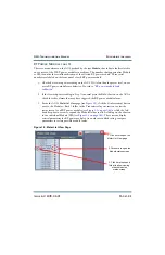
5. If the measurements in
and
are satisfactory, but the RF power module
continues to display alarms when installed in the transmitter, replace the RF power
module.
Resistance measurements
Complete the following resistance measurements for each suspect RF power module.
See
to identify the power MOSFETs on the RF power module.
1. Remove fuse F1 from its holder and measure its resistance using a digital multimeter. A
blown fuse will measure an open circuit. If the fuse is OK, return it to its holder.
2. For each power amplifier MOSFET (Q7 through Q10) and each modulator MOSFET
(Q11, Q12 and Q13), use a digital multimeter to make the following resistance
measurements. Note that Q7 through Q10 have screw-head terminals and Q11
through Q13 have solder pads (see
• Check for 1,000
between the gate and source.
• Check for an open circuit between the gate and drain.
is not satisfactory, replace the affected power amplifier
MOSFET (see
“Power Amplifier FET replacement”
) or modulator MOSFET (see
“Modulator FET or Free-Wheel Diode replacement” on page 1-62
), as applicable, or
replace the RF power module.
Protection Diode checks
Complete the following protection
diode checks for each suspect RF power module.
See
to identify the protection diode on the RF power module.
1. Use a digital multimeter (on its diode setting) to check protection diode CR9, noting
the anode (A) and cathode (K) markings (see
):
• Check for a voltage of between 0.5 and 0.8 V with multimeter test leads in the
forward bias orientation (+ on anode, - on cathode).
• Check for an open circuit with multimeter test leads in the reverse bias orientation
(- on anode, + on cathode).
Содержание NX50
Страница 1: ...NX50 Transmitter Troubleshooting Manual Document NHB NX50 TRB Issue 6 0 2019 04 01 Status Standard...
Страница 2: ......
Страница 4: ......
Страница 8: ...NX50 Troubleshooting Manual Page viii Issue 6 0 2019 04 01...
Страница 10: ...NX50 Troubleshooting Manual Page x Issue 6 0 2019 04 01...
Страница 108: ...NX50 Troubleshooting Manual Responding to alarms Page 1 98 Issue 6 0 2019 04 01...
Страница 153: ...NX50 Troubleshooting Manual Reading Electrical Schematics Page 4 6 Issue 6 0 2019 04 01...
Страница 184: ...Issue 6 0 2019 04 01 MD 4 Figure MD 4 NAPI95A 01 Power Module Interface PWB...
Страница 188: ...Issue 6 0 2019 04 01 MD 8 Figure MD 8 NAPI106 Remote Interface PWB...
Страница 192: ...Issue 6 0 2019 04 01 MD 12 Figure MD 12 NAPI98 RF Drive Distribution PWB...
Страница 194: ...Issue 6 0 2019 04 01 MD 14 Figure MD 14 NAX243B 01 B Distribution Assembly J1 R1 R2 R3 R4 Front View Rear View...
Страница 198: ...Issue 6 0 2019 04 01 MD 18 Figure MD 18 Fan Tray Assembly 207 8133 B1 B2 J1 AIR FLOW AIR FLOW...
Страница 200: ...Issue 6 0 2019 04 01 MD 20 Figure MD 20 Current Probe 207 6213 10 Front View Rear View T1 R1 R2 R3 R4 J1 P1...
Страница 201: ...Issue 6 0 2019 04 01 MD 21 Figure MD 21 NAFP106B 01 Directional Coupler A1 DETAIL...
Страница 204: ......


