


NX50 Troubleshooting Manual
Responding to alarms
Page 1-76
Issue 6.0 2019-04-01
6. Obtain a replacement RF Drive Distribution PWB (Nautel Part # NAPI98).
7. Reverse
to install the replacement PWB. Ensure all connections
are tight. For connector mating assistance, refer to the connector mating tables in
Section 3, “Wiring/connector lists” on page 3-1
8. Close and lock the rear door. Turn on (enable) the ac power source and set the
transmitter to it RF ON state. Ensure any previous alarms have cleared.
Rack Interface PWB replacement
See
.
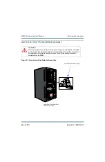
1. Set the transmitter to its RF Off state and turn off (disable) the ac power at the source.
Lift the air filter (slide it up) to verify the LEDs on the power module interface PWBs
are off (green when on), indicating the B+ capacitors are discharged. Open the rear
door of the cabinet and verify the three ac indicator LEDs on the rectifier assembly are
off (amber when on). For additional safety, measure the dc voltage across the + and -
terminals of any of the large, electrolytic capacitors on the floor of the cabinet as well
as the line-to-line and line-to-ground voltages at the ac input terminals. There should be
little or no ac or dc voltage. DO NOT PROCEED if either the ac or dc voltage is
greater than 5V.
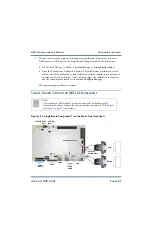
2. Carefully remove and retain the six (6) M3 screws used to secure the rack interface
cover (see
). Disconnect the two (2) white wires that pass
through the rack interface cover noting the label and connection point for each.
Remove the rack interface cover to access the PWBs.
3. Remove the interconnecting RF Drive Distribution PWB (see
4. Disconnect all cables attached to the Rack Interface PWB, taking note of the connector
labels on the cables and the PWB.
5. Carefully remove and retain the four (4) male/female pillars using a 6mm nut driver or
a small adjustable wrench, and the two (2) M3 mounting screws.
WARNING:
Lethal voltages exist inside the transmitter when the power is turned
on. Turn off (disable) and lock out the power at the source and verify
no dangerous ac or dc voltages are present before removing any
connections or PWBs.
Содержание NX50
Страница 1: ...NX50 Transmitter Troubleshooting Manual Document NHB NX50 TRB Issue 6 0 2019 04 01 Status Standard...
Страница 2: ......
Страница 4: ......
Страница 8: ...NX50 Troubleshooting Manual Page viii Issue 6 0 2019 04 01...
Страница 10: ...NX50 Troubleshooting Manual Page x Issue 6 0 2019 04 01...
Страница 108: ...NX50 Troubleshooting Manual Responding to alarms Page 1 98 Issue 6 0 2019 04 01...
Страница 153: ...NX50 Troubleshooting Manual Reading Electrical Schematics Page 4 6 Issue 6 0 2019 04 01...
Страница 184: ...Issue 6 0 2019 04 01 MD 4 Figure MD 4 NAPI95A 01 Power Module Interface PWB...
Страница 188: ...Issue 6 0 2019 04 01 MD 8 Figure MD 8 NAPI106 Remote Interface PWB...
Страница 192: ...Issue 6 0 2019 04 01 MD 12 Figure MD 12 NAPI98 RF Drive Distribution PWB...
Страница 194: ...Issue 6 0 2019 04 01 MD 14 Figure MD 14 NAX243B 01 B Distribution Assembly J1 R1 R2 R3 R4 Front View Rear View...
Страница 198: ...Issue 6 0 2019 04 01 MD 18 Figure MD 18 Fan Tray Assembly 207 8133 B1 B2 J1 AIR FLOW AIR FLOW...
Страница 200: ...Issue 6 0 2019 04 01 MD 20 Figure MD 20 Current Probe 207 6213 10 Front View Rear View T1 R1 R2 R3 R4 J1 P1...
Страница 201: ...Issue 6 0 2019 04 01 MD 21 Figure MD 21 NAFP106B 01 Directional Coupler A1 DETAIL...
Страница 204: ......


