451
/
838
Nations Technologies Inc.
Tel
:
+86-755-86309900
:
Address: Nations Tower, #109 Baoshen Road, Hi-tech Park North.
Nanshan District, Shenzhen, 518057, P.R.China
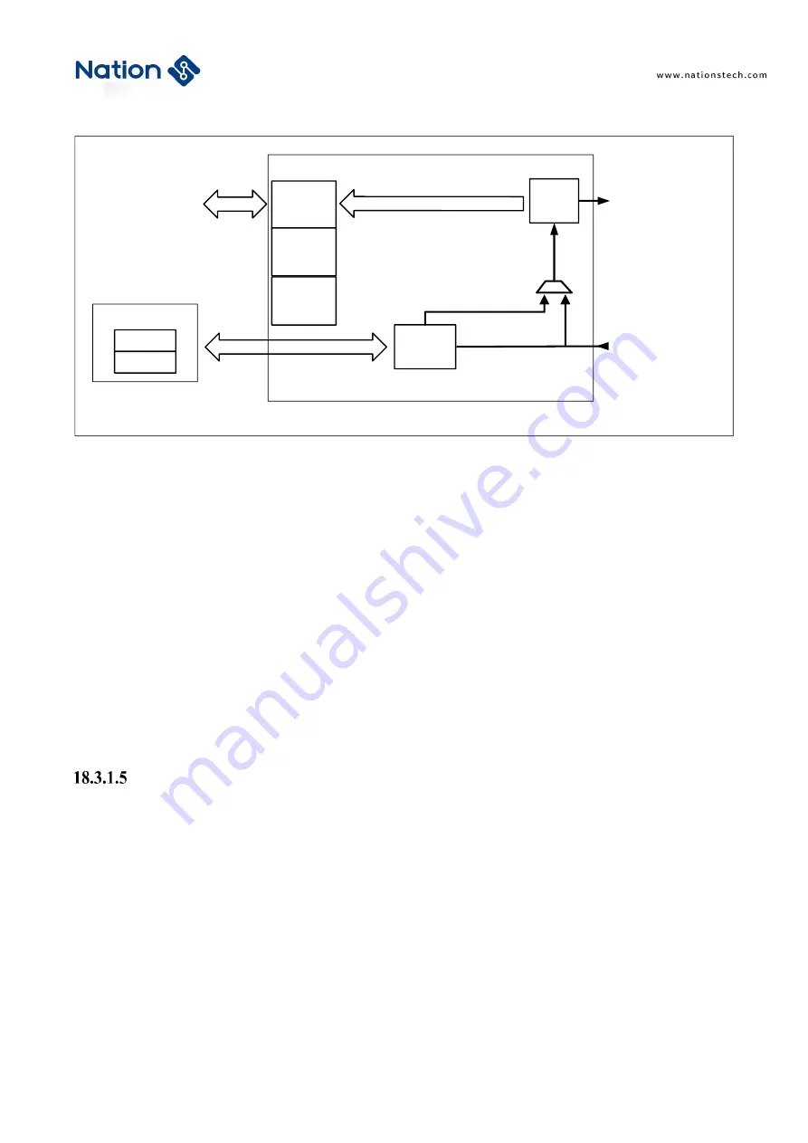
Figure 18-12 Data Channel
The data bus width of the card can be configured in the clock control register (SDIO_CLKCTRL). When the data
width is 4 bits (SDIO_ CLKCTRL.BUSMODE bit is 0b01), 4 bits of data will be transmitted on the four data signal
lines SDIO_DAT[3:0] in each clock cycle; when the data width is 8 bits (SDIO_ CLKCTRL.BUSMODE bit is 0b10),
8-bit data will be transmitted on the eight data signal lines SDIO_DAT[7:0] per clock cycle; when the data width is
1 bit (SDIO_CLKCTRL.BUSMODE bit is 0b00) or the bus mode is not selected , only 1 bit of data is transmitted on
SDIO_DAT0 per clock cycle.
The data transmission flow is controlled by the Data Channel State Machine (DPSM). Data transfer begins after a
write to the SDIO_DATCTRL register and setting the SDIO_DATCTRL.DATEN bit to 1. When the
SDIO_DATCTRL.DATDIR bit is 0, the data is from the controller to the card, and the DPSM enters the Wait_S state.
If there is data in the transmit FIFO, the DPSM enters the transmit state, and the data channel subunit starts to send
data to the card; when the DATDIR bit is When 1, the data is from the card to the controller, the DPSM enters the
Wait_R state, when the start bit is received, the DPSM enters the receiving state and waits for the start bit, and the
data channel subunit starts to receive data from the card. Data units can also generate data status flags (defined in the
SDIO_STS register).
Data path state machine (DPSM)
The data channel state machine (DPSM) operates at the SDIO_CLK frequency, and the card bus signal is
synchronized with the rising edge of SDIO_CLK. DPSM has 6 states, as shown in the following figure:
To control unit
Shift
register
Status flag
Control
logic
Command
timer
Send
Receive
CRC
Data FIFO
SDIO_DAT in
[7:0]
SDIO_DAT out [7:0]
Data channel


