195
6-4. Hints for Programming High-level Instructions
■
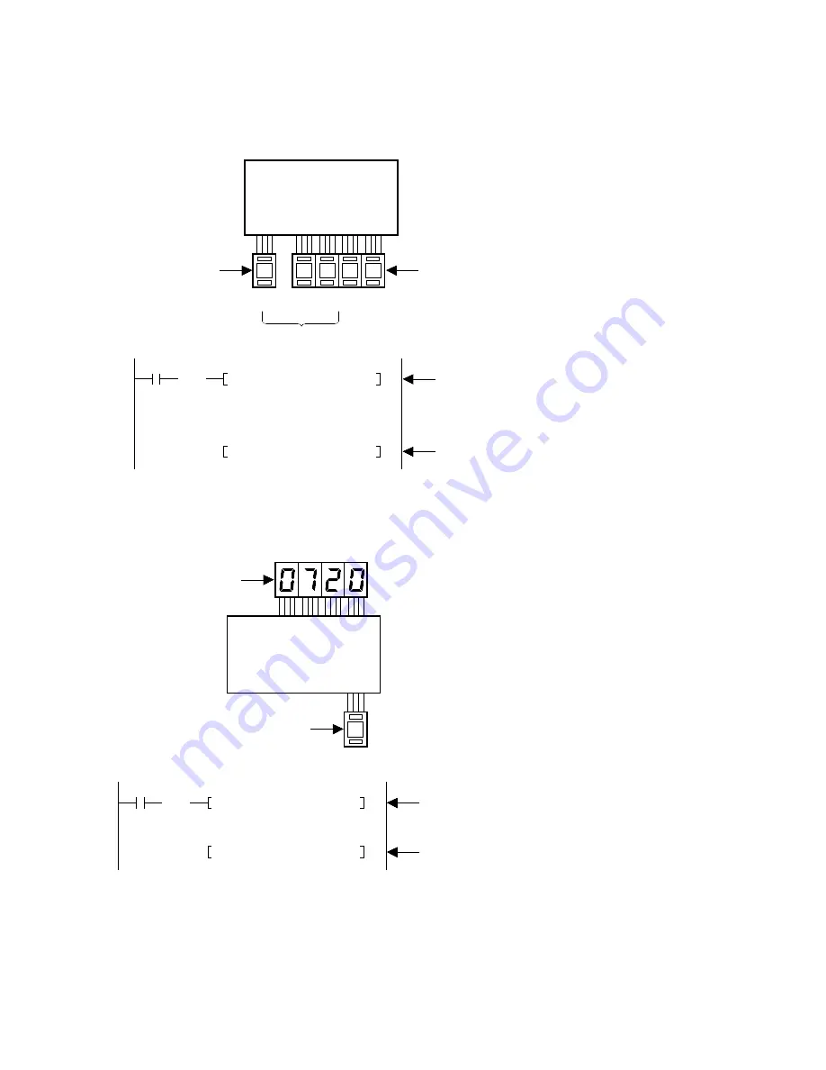
Setting/Displaying data according to digital switch input
Example 1: When setting the timer set (preset) values input from the digital switch
• The selection of the timer instruction number is performed using the input from the digital switches
(WX1). The timer preset (set) value can be input from the digit switches (WX0).
Example 2: When displaying the data in the programmable controller
• The elapsed value of the timer instruction is displayed on the 7-segment digital indicators (WY0).
The timer instruction number is selected by the input from the digital switch (WX1).
1
FP1 Programmable
Controller
Timer number
WX1
WY0
Digital switch
R1
F81 BIN, WX1, IX
( DF )
F80 BCD, IXEV0, WY0
The timer instruction number input from WX1 (BCD) is
converted to binary and stored in IX.
The timer elapsed (count) value at the address specified
by IX and EV0 is converted to BCD and output to WY0.
Timer elapsed
value data
7-segment
indicator
2
0 7 9 4
FP1 Programmable
Controller
Timer set value data
Timer number
WX1
%
%
%
%
%
%
%
WX0
Digital switch
R0
F81 BIN, WX1, IX
( DF )
F81 BIN, WX0, IXSV0
Each time R0 turns ON, the settings of the digital switches
[WX0 (BCD data)] are converted to binary data and stored in
the timer preset (set) value area specified by SV0 and IX.
The timer instruction number input from WX1 (BCD) is
converted to binary and stored in IX.
The timer preset (set) value input from WX0 (BCD) is converted
to binary and stored in the address specified by IX and SV0.
Содержание FP1
Страница 1: ...PROGRAMMABLE CONTROLLER FP1 is a global brand name of Matsushita Electric Works Hardware ...
Страница 28: ...20 ...
Страница 98: ...90 ...
Страница 150: ...142 ...
Страница 208: ...200 ...
Страница 226: ...218 ...
Страница 280: ...272 ...


