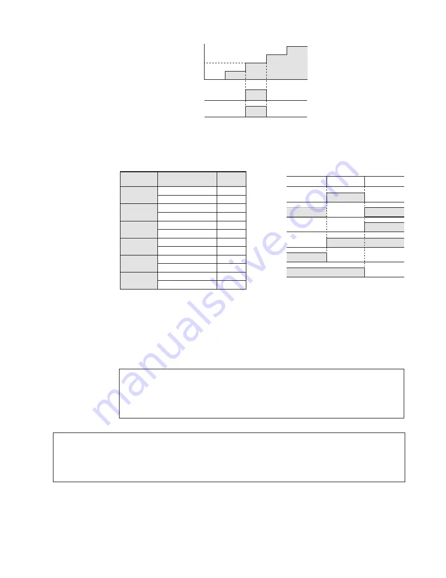
Description
• Compares the double word data specified by S1 and S1+1, with the double word data specified
by S2 and S2+1, according to the comparative conditions.
The contact goes ON/OFF depending on the result of the comparison.
• The result of the comparison operation is as follows:
■
Flag condition
• Error flag (R9007):
Turns ON and keeps the ON state when the area specified using the
index modifier exceeds the limit. The error address is transferred to
DT9017 and held. (See notes below.)
• Error flag (R9008):
Turns ON for an instant when the area specified using the index
modifier exceeds the limit. The error address is transferred to DT9018.
(See notes below.)
Notes:
Notes:
• The Start comparison instructions
STD =
,
STD <>
,
STD >
,
STD >=
,
STD <
, and
STD <=
are
programmed from the bus line.
• This instruction can be input only with FP Programmer
II
or NPST-GR version 3.1 or later.
• When processing 32-bit data, the higher 16-bit areas (S1+1, S2+1) are automatically decided if the lower
16-bit areas (S1, S2) are specified.
• Special data registers DT9017 and DT9018 are available only for FP1s with CPU
version 2.7 or later. (All FP1s with a suffix “B” on the part number have this function.)
• When using special internal relay R9008 as the flag for this instruction, be sure to
program the flag at the address immediately after the instruction.
• Refer to page 223, “8-3. Table of Special Internal Relays”, for details about error flags.
ON
OFF
STD <>
STD =
ON
OFF
ON
OFF
ON
OFF
ON
OFF
ON
OFF
ON
OFF
STD =
STD <>
STD >
STD >=
STD <
STD <=
Comparative
instruction
Comparative
condition
ON
OFF
ON
OFF
STD >=
STD >
ON
OFF
ON
OFF
STD <=
STD <
(S1+1, S1) < (S2+1, S2)
ON
OFF
Contact
operation
Condition
(S1+1, S1) =
(S1+1, S1)
(S1+1, S1)
(S1+1, S1) =
(S1+1, S1) >
(S1+1, S1)
(S1+1, S1)
(S1+1, S1) <
(S1+1, S1) <
(S1+1, S1)
(S1+1, S1)
(S1+1, S1) >
(S2+1, S2)
(S2+1, S2)
(S2+1, S2)
(S2+1, S2)
(S2+1, S2)
(S2+1, S2)
(S2+1, S2)
(S2+1, S2)
(S2+1, S2)
(S2+1, S2)
(S2+1, S2)
(S2+1, S2)
(S1+1, S1) = (S2+1, S2) (S1+1, S1) > (S2+1, S2)
ON [(DT1, DT0) = K50]
OFF [(DT1, DT0)
K50]
ON
OFF
K30
K50
K60
K70
K40
STD =
Y0
(DT1, DT0)
■
Time chart
134
5-3. Description of Basic Instructions
Содержание FP1
Страница 1: ...PROGRAMMABLE CONTROLLER FP1 is a global brand name of Matsushita Electric Works Hardware ...
Страница 28: ...20 ...
Страница 98: ...90 ...
Страница 150: ...142 ...
Страница 208: ...200 ...
Страница 226: ...218 ...
Страница 280: ...272 ...


