235
8-5. System Registers
Address
402
403
Name of system register
Pulse catch input function
settings
Pulse of 500 µs or
more duration
Interrupt trigger settings
Default
value
H0
H0
Description
This register specifies the pulse catch inputting function
availabilities for X0 to X7.
• Settings
0: standard input mode
1: pulse catch input mode
Input the specific value in an order so that the bit
corresponding to each input becomes “1” when you use the
pulse catch function.
• Setting range
C14/C16 series (4 inputs X0 to X3):
C24/C40/C56/C72 series (8 inputs X0 to X7):
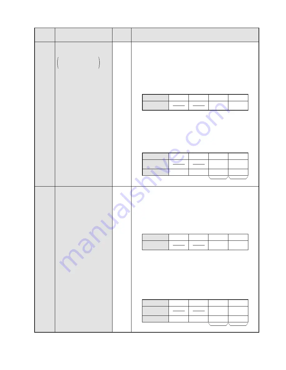
EXAMPLE:
If the pulse catch function is used for inputs X3, X4, and
X5 of the C24 series, input H38 as follows:
This register specifies inputs of the FP1 as interrupt triggers.
• Settings
0: standard input mode
1: interrupt input mode
Input the specific value in an order so that the bit
corresponding to each input becomes “1” when you use
interrupt programs.
• Setting range
C14/C16 series: Not available
C24/C40/C56/C72 series
(8 inputs X0 to X7): H0 to HFF
EXAMPLE:
If the interrupt input function is used for inputs X1 and X2
of the C24 series, input H6 as follows:
H 6
Bit position
7
4
•
•
X7
X4
X6 X5
Corresponding
input
3
0
•
•
11
8
•
•
15
12
•
•
X3
X0
X2 X1
System register 403
Bit position
Corresponding
input
Data input
0 0 0 0
0 0 0 0
0 0 0 0
0 1 1 0
7
4
•
•
X7
X4
X6 X5
3
0
•
•
11
8
•
•
15
12
•
•
X3
X0
X2 X1
System register 403
Bit position
7
4
•
•
X7
X4
X6 X5
Corresponding
input
3
0
•
•
11
8
•
•
15
12
•
•
X3
X0
X2 X1
System register 402
Bit position
Corresponding
input
Data input
0 0 0 0
0 0 0 0
0 0 1 1
1 0 0 0
H 3
8
7
4
•
•
X7
X4
X6 X5
3
0
•
•
11
8
•
•
15
12
•
•
X3
X0
X2 X1
System register 402
H0 to HF
H0 to HFF
Содержание FP1
Страница 1: ...PROGRAMMABLE CONTROLLER FP1 is a global brand name of Matsushita Electric Works Hardware ...
Страница 28: ...20 ...
Страница 98: ...90 ...
Страница 150: ...142 ...
Страница 208: ...200 ...
Страница 226: ...218 ...
Страница 280: ...272 ...


