2.3 Connected signals
2-19
2.3.4 Back check circuit
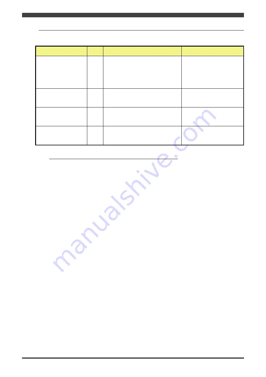
Table 2-15 Back check
Signal name
Circuit
code
Description
Electrical specifications
Robot power supply back
check 1+
Robot power supply back
check 1-
BK1+
BK1-
Signal from magnet switch “b” contact.
Signal for detecting the welding (back
check) of the magnet switch
When being used as a slave unit, this is
regarded as a weld stuck detection signal
for "Slave failure" output signal (back
check).
Photo-coupler input
Rating DC26V
Input current 5mA
Over current protection provided
General safety output 1
back check 1+
back check 1-
BK2+
BK2-
Signal from external safety relay and
magnet switch “b” contact
Signal for detecting the welding (back
check) of the magnet switch
Photo-coupler input
Rating DC26V
Input current 5mA
Over current protection provided
General safety output 2
back check 2+
back check 2-
BK3+
BK3-
Signal from external safety relay and
magnet switch “b” contact
Signal for detecting the welding (back
check) of the magnet switch
Photo-coupler input
Rating DC26V
Input current 5mA
Over current protection provided
General safety output 3
back check 3+
back check 3-
BK4+
BK4-
Signal from external safety relay and
magnet switch “b” contact
Signal for detecting the welding (back
check) of the magnet switch
Photo-coupler input
Rating DC26V
Input current 5mA
Over current protection provided
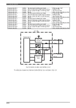
Back check circuit with over current protection and input diagnosis
A back check circuit is provided in the RMU in order to monitor the magnet switch contacts which are tripped
by the safety outputs. In the back check circuit, a safety contact (“b” contact) driven by the safety output and an
auxiliary contact (“b” contact) of the magnet switch are connected in series so that if the main contact ("a"
contact) of the relay melts down making it impossible to release the contact, the other safety output can still be
turned off to shut off drive power surely and stop the robot safely.
*) If the back check input is not inputted, a back check fault will be detected when the output is ON.
Содержание RMU20-20
Страница 2: ......
Страница 6: ...Contents 4 ...
Страница 8: ......
Страница 26: ...1 4 EC DECLARATION OF CONFORMITY FOR MACHINERY 1 18 NOTE ...
Страница 68: ...2 9 Enabling RMU 2 40 NOTE ...
Страница 70: ......
Страница 86: ...3 2Operation procedure 3 16 Top Display Form Limit Side Display Sphere Limit Side Display Form Limit ...
Страница 100: ...3 4 Setting when a slider unit is used 3 30 NOTE ...
Страница 102: ......
Страница 138: ...4 4Approval 4 36 8 Approval is completed The following screen will be displayed ...
Страница 144: ......
Страница 154: ...5 4Trouble shooting 5 10 NOTE ...
Страница 156: ......
Страница 166: ...6 4Trouble shooting 6 10 NOTE ...
Страница 168: ......
Страница 189: ......


