4.5Setting of disconnection
4-37
4.5 Setting of disconnection
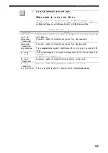
In case of “Axis disconnection utility” and or so, RMU will detect the encoder error because the specified axis
is physically disconnected. Therefore, monitoring function must be set to disabled for this specified axis before
utilizing these utility.
DANGER
Concerning the axis that the "Connection" is set to "1"(=disconnection), the all of monitoring
function is disabled.
Therefore, pay utmost attention to operate the robot.
If the specified axis moves unexpectedly, coming into contact with or getting caught in the
robot will result in death or serious injury.
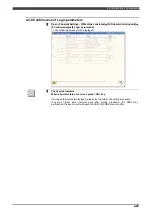
And, after using the "Axial separation" menu, do not forget to make the setting that was
changed here to the original setting. If this is forgotten, the robot may not work normally.
4.5.1 Setting of disconnection
1
SPECIALIST
or higher operator class is necessary to change this parameter.
2
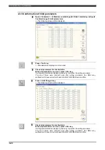
Open <Constants> - [3 Machine constants]
–
[34 Robot monitoring unit]
–
[1
Setting]
–
[2 Axis parameters].
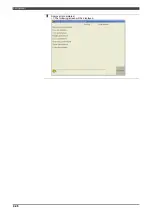
>> The following screen will be displayed.
(NOTE) The parameters are displayed in the following order;
JT1 JT2 JT3
JT4 JT5 JT6
JT7 JT8
3
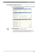
Align the cursor to the axis of [Connection] line which to be disconnected, and
enter [1]. Also check another axis is set to [0].
Содержание RMU20-20
Страница 2: ......
Страница 6: ...Contents 4 ...
Страница 8: ......
Страница 26: ...1 4 EC DECLARATION OF CONFORMITY FOR MACHINERY 1 18 NOTE ...
Страница 68: ...2 9 Enabling RMU 2 40 NOTE ...
Страница 70: ......
Страница 86: ...3 2Operation procedure 3 16 Top Display Form Limit Side Display Sphere Limit Side Display Form Limit ...
Страница 100: ...3 4 Setting when a slider unit is used 3 30 NOTE ...
Страница 102: ......
Страница 138: ...4 4Approval 4 36 8 Approval is completed The following screen will be displayed ...
Страница 144: ......
Страница 154: ...5 4Trouble shooting 5 10 NOTE ...
Страница 156: ......
Страница 166: ...6 4Trouble shooting 6 10 NOTE ...
Страница 168: ......
Страница 189: ......

