2.3 Connected signals
2-18
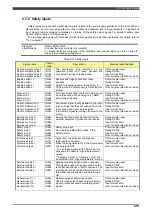
2.3.3 Safety outputs
Electrical
specifications
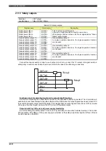
FET output
Max. DC30V, 100mA
Table 2-14 Safety outputs
Signal name
Circuit code
Description
Robot power ON 1+
Robot power ON 1-
Robot power ON 2+
Robot power ON 2-
OUT1A+
OUT1A-
OUT1B+
OUT1B-
This is robot power ON signal.
Connect to magnet switch contact for servo drive.
When being used as a slave unit, this is regareded as "Slave
failure" output signal.
General safety output 11+
General safety output 11-
General safety output 12+
General safety output 12-
OUT2A+
OUT2A-
OUT2B+
OUT2B-
General safety output 1.
An output operation based on the logical operation function
can be used.
General safety output 21+
General safety output 21-
General safety output 22+
General safety output 22-
OUT3A+
OUT3A-
OUT3B+
OUT3B-
General safety output 2.
An output operation based on the logical operation function
can be used.
General safety output 31+
General safety output 31-
General safety output 32+
General safety output 32-
OUT4A+
OUT4A-
OUT4B+
OUT4B-
General safety output 3.
An output operation based on the logical operation function
can be used.
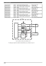
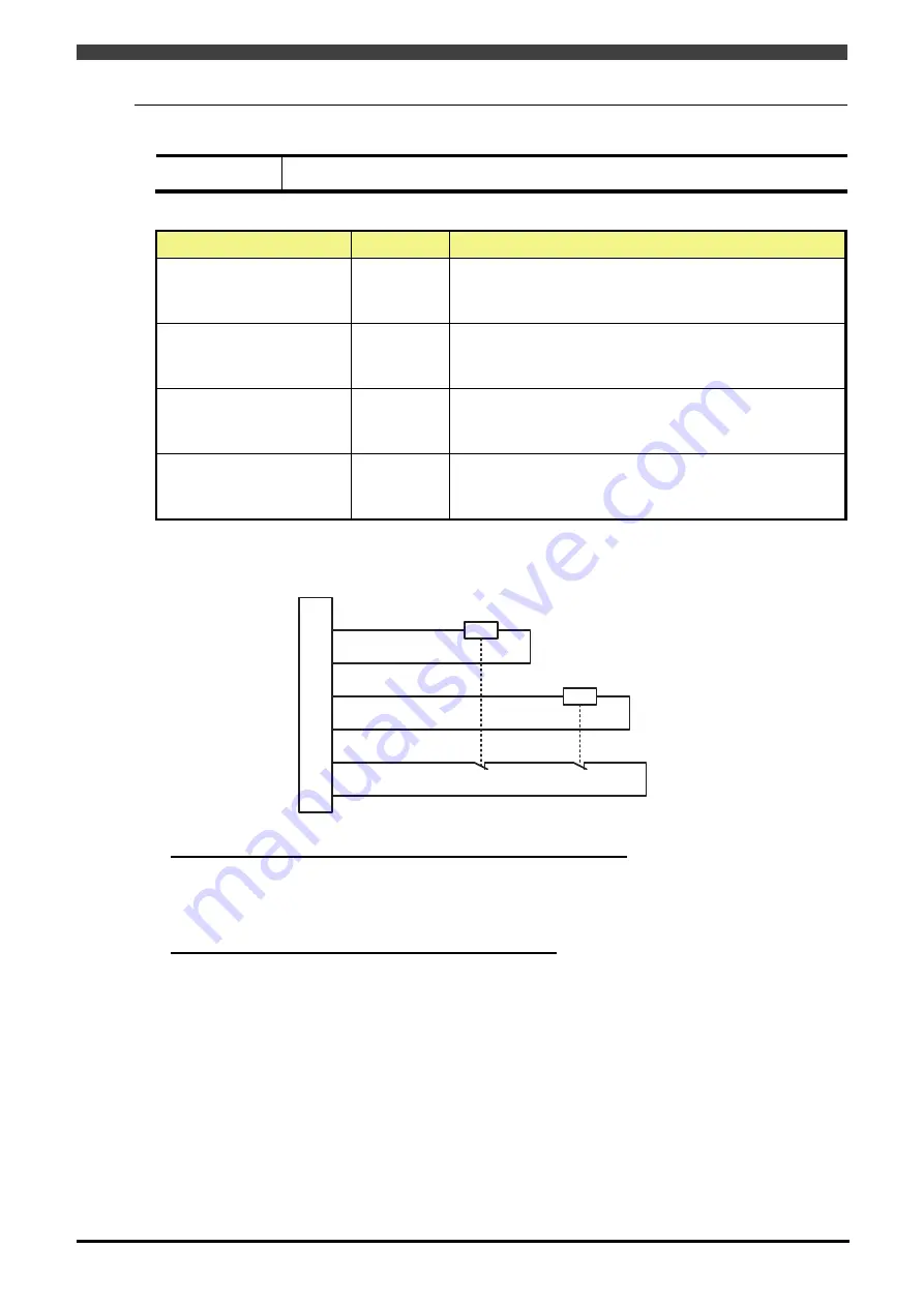
Connect the magnet switch or relay to each output circuit. Also, connect the “b”-contact of magnet switch or
safety relay in series to each back-check input. Refer to the case of the following connections:
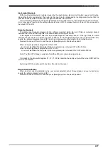
Feedback circuit for detecting trouble in the output shutoff functions
A circuit for monitoring the output status of each of the redundant outputs is provided. The circuit makes it
possible to check these statuses using the software of the RMU when the output signals have been turned OFF
to ascertain the safety output shutoff capability. If it is judged that one output signal cannot be set OFF by trouble
of any type, the other signal can be set to OFF to turn off the safety output.
Output shutoff by CPU error and power supply monitoring
A circuit enabling the safety output to be shut off by hardware means when troubles develop in the control
CPU operation of the RMU or in the power supply is provided, so the safety output is surely shut off even if these
troubles develop in the RMU.
OUTxA+
OUTxA-
OUTxB+
OUTxB-
BKx+
BKx-
Relay1
Relay2
Содержание RMU20-20
Страница 2: ......
Страница 6: ...Contents 4 ...
Страница 8: ......
Страница 26: ...1 4 EC DECLARATION OF CONFORMITY FOR MACHINERY 1 18 NOTE ...
Страница 68: ...2 9 Enabling RMU 2 40 NOTE ...
Страница 70: ......
Страница 86: ...3 2Operation procedure 3 16 Top Display Form Limit Side Display Sphere Limit Side Display Form Limit ...
Страница 100: ...3 4 Setting when a slider unit is used 3 30 NOTE ...
Страница 102: ......
Страница 138: ...4 4Approval 4 36 8 Approval is completed The following screen will be displayed ...
Страница 144: ......
Страница 154: ...5 4Trouble shooting 5 10 NOTE ...
Страница 156: ......
Страница 166: ...6 4Trouble shooting 6 10 NOTE ...
Страница 168: ......
Страница 189: ......


