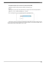
1.1 Outline
1-12
1.3.4 Connection of safety inputs
Electrical
specifications
Rating DC26V, 5mA max
Connect the relay contacts (dry contacts).
To prevent defective contact and other problems, use a device which can turn on and off
the very small load specified above.
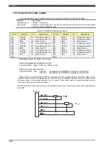
These input signals must have redundant circuit. The two separat signals with redundant contact inputs must
perform identical operations. Connect separate contacts between pins "INA+" – "INA-" and "INB+" – "INB-" for
each input as shown in the Fig.1-2. Bear in mind that the signals cannot be connected in ways such as the one
shown in Fig.1-3.
[Example] In case of robot emergency stop inputs
Fig.1-3 Connection diagram of safety input signals
Fig.1-4 Example of how the safety input signals cannot be connected
Connection of monitor input
Electrical
specification
Rating DC26V, 5mA
Connect the dry contacts.
To prevent defective contact and other problems, use a device which can turn on and off
the very small load specified above.
Fig. 1-5 Connection diagram of the monitor input signal
External input
External input
TBX-1 (RMU input)
TBX-1 (RMU input)
External input
TBX-1 (RMU input)
External input
TBX-1 (RMU input)
Содержание RMU20-20
Страница 2: ......
Страница 6: ...Contents 4 ...
Страница 8: ......
Страница 26: ...1 4 EC DECLARATION OF CONFORMITY FOR MACHINERY 1 18 NOTE ...
Страница 68: ...2 9 Enabling RMU 2 40 NOTE ...
Страница 70: ......
Страница 86: ...3 2Operation procedure 3 16 Top Display Form Limit Side Display Sphere Limit Side Display Form Limit ...
Страница 100: ...3 4 Setting when a slider unit is used 3 30 NOTE ...
Страница 102: ......
Страница 138: ...4 4Approval 4 36 8 Approval is completed The following screen will be displayed ...
Страница 144: ......
Страница 154: ...5 4Trouble shooting 5 10 NOTE ...
Страница 156: ......
Страница 166: ...6 4Trouble shooting 6 10 NOTE ...
Страница 168: ......
Страница 189: ......


