1-4
Motorola RF Switch Systen Reference
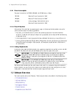
1.1.1.1 Power Consumption
The power consumption for RFS7000, RFS6000, and RFS4000 are as follows:
1.1.1.2 Power Protection
To best protect the switch from unexpected power surges or other power-related problems, ensure the
switch installation meets the following guidelines:
•
If possible, use a dedicated circuit to protect data processing equipment
. Commercial electrical
contractors are familiar with wiring for data processing equipment and can help with the load balancing
of dedicated circuits.
•
Install surge protection
. Use a surge protection device between the electricity source and the switch.
•
Install an Uninterruptible Power Supply (UPS)
. A UPS provides continuous power during a power outage.
Some UPS devices have integral surge protection. UPS equipment requires periodic maintenance to
ensure reliability.
1.1.1.3 Cabling Requirements
A minimum of one category 6 Ethernet cables (not supplied) are required to connect the switch to the LAN
and WLAN. The cable(s) are used with the Ethernet ports on the front panel of the switch.
The console cable included with the switch connects the switch to a computer running a serial terminal
emulator program to access the switch’s
Command Line Interface
(CLI) for initial configuration. An initial
configuration is described within the
Installation Guide
shipped with each switch.
1.2 Software Overview
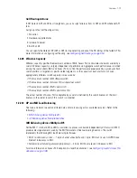
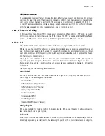
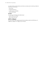
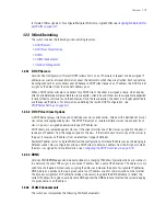
The switch includes a robust set of features. The features are listed and described in the following sections:
•
Infrastructure Features
•
Wireless Switching
•
Wired Switching
•
Management Features
•
Security Features
•
Supported Access Ports/Points
RFS7000
Maximum Power Consumption: 100W
RFS6000
Maximum Power Consumption: 300W
RFS4000
AC Input Voltage: 100-240 VAC 50/60 Hz
Maximum Power Consumption: 120W
SWITCH NOTE:
On an RFS6000 and RFS7000, Motorola recommends connecting via the
Management Ethernet (ME) interface to better ensure secure and easier management.
The ME interface is connected to the management VLAN, and is therefore separate from
production VLANs.
SWITCH NOTE:
On the RFS4000 and RFS6000 the Uplink (UP) port is the preferred
method of connecting the switch to the network. The Uplink port has its own dedicated
1Gbps connection which is unaffected by internal traffic across the GE ports.
Содержание RFS Series
Страница 1: ...M Motorola RFS Series Wireless LAN Switches WiNG System Reference Guide ...
Страница 10: ...TOC 8 Motorola RF Switch System Reference Guide ...
Страница 56: ...2 8 Motorola RF Switch System Reference ...
Страница 334: ...5 52 Motorola RF Switch System Reference 2 Select the MU Status tab ...
Страница 510: ...7 32 Motorola RF Switch System Reference Guide ...
Страница 534: ...8 24 Motorola RF Switch System Reference Guide ...
Страница 570: ...C 14 Motorola RF Switch System Reference Guide ...
Страница 589: ......
Страница 590: ...MOTOROLA INC 1303 E ALGONQUIN ROAD SCHAUMBURG IL 60196 http www motorola com 72E 132942 01 Revision C December 2010 ...


