4-14
Motorola RF Switch System Reference Guide
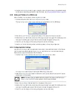
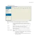
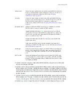
3. Select a record from the table and click the
Edit
button to modify the record. For more information, see
Modifying a Virtual Interface on page 4-15
.
4. Select a record from the table and click the
Delete
button to remove the configuration from the list of
switch virtual interfaces.
5. Click the
Add
button to add a new configuration to the switch virtual interface. For more information, see
Adding a Virtual Interface on page 4-14
.
6. Select an interface and click the
Startup
button to invoke the selected interface the next time the switch
is booted.
7. Select an interface and click the
Shutdown
button to disable the selected interface.
4.4.1.1 Adding a Virtual Interface
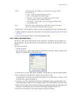
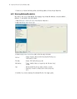
To add a new switch virtual interface:
1. Select
Network
>
Switch Virtual Interface
from
the main tree menu.
2. Select the
Configuration
tab.
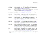
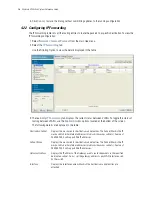
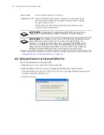
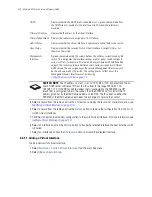
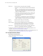
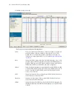
DHCP
Displays whether the DHCP client is enabled or not. A green check mark defines
the DHCP client as enabled for the interface. A red X means the interface is
disabled.
Primary IP Address
Displays the IP address for the virtual interface.
Primary Subnet Mask
Displays the subnet mask assigned for this interface.
Admin Status
Displays whether the virtual interface is operational and available to the switch.
Oper Status
Displays whether the selected Switch Virtual Interface is currently (Up) or not
(Down) on the switch.
Management
Interface
A green checkmark within this column defines this VLAN as currently used by the
switch. This designates the interface settings used for global switch settings in
case of conflicts. For example, if multiple SVIs are configured with DHCP enabled
on each, the switch could have multiple domain names assigned from different
DHCP servers.The one assigned over the selected Management Interface would
be the only one used by the switch. This setting does not affect any of the
Management Access Interfaces configured using
Configuring Access Control on page 7-2
.
SWITCH NOTE:
The IP address on vlan1 is set to "192.168.0.1/24" by default and the on-
board DHCP server will serve IPs from this IP subnet in the range 192.168.1.150-
192.168.1.170. If the DSL or Cable modem that is connected to the RFS4000 via UP1
(vlan2100) is configured to be in the subnet, then the RFS4000 will not install the IP
address given out by the DSL/Cable modem on vlan2100. The IP subnet on either the
RFS4000 or the DSL/Cable modem needs to be changed to resolve the conflict.
Содержание RFS Series
Страница 1: ...M Motorola RFS Series Wireless LAN Switches WiNG System Reference Guide ...
Страница 10: ...TOC 8 Motorola RF Switch System Reference Guide ...
Страница 56: ...2 8 Motorola RF Switch System Reference ...
Страница 334: ...5 52 Motorola RF Switch System Reference 2 Select the MU Status tab ...
Страница 510: ...7 32 Motorola RF Switch System Reference Guide ...
Страница 534: ...8 24 Motorola RF Switch System Reference Guide ...
Страница 570: ...C 14 Motorola RF Switch System Reference Guide ...
Страница 589: ......
Страница 590: ...MOTOROLA INC 1303 E ALGONQUIN ROAD SCHAUMBURG IL 60196 http www motorola com 72E 132942 01 Revision C December 2010 ...

