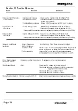
Edge & Crunch Sensors
Check supply voltage
Black lead of meter on tab IC8 (Main PCB)
- Transmitters
Should read 1.3Vdc
Red lead of meter on red wire of CN8 and
yellow wire of CN16
To Adjust these voltages
Adjust VR4 Edge sensor & VR8 Crunch sensor.
Crunch Sensor
Check voltage 1Vdc
Meter across Red/Black of CN16 (Obstruct
- Receiver
Beam and Voltage will rise to approx 4.2 Vdc)
Voltage will increase/decrease by adjusting intensity of transmitter (pot VR8)
Edge Sensor
Check voltage 0.46Vdc
Meter across Red/Blue of CN8(Obstruct
- Receiver
Beam and Voltage will rise to approx 5 Vdc)
Voltage will increase/decrease by adjusting intensity of transmitter (pot VR4)
Safety Circuit Faulty
Check Voltage on
Any Switch or Wire, Open circuit will be 0Vdc
No Drive.
CN7 =10/12 Vdc
To Check PCB.
Black lead of meter on tab IC8 (Main PCB) Red lead of
meter on brown wire plug6 CN7 should read 12Vdc
To Check Cable
Unplug CN7 (meter set to Ohms) place probes
across plug If no continuity then check each switch.
Error Double Sheet
Check link on CN13 is correct.
Replace link, check wiring diagram.
Detected. Error 3
Slot Sensor Blade
CN3
Black lead of meter on Yellow (ground)
Red lead of meter on Green = 0.2Vdc obstructed
Approx 4Vdc not obstructed.
Red lead of meter on Blue = 5Vdc
Red lead of meter on Red = 1.2Vdc
Home Position Switch
Remove plug from CN13
Check continuity across wires (make and break switch)
Section 11 Trouble Shooting
Fault
Reason
Solution
Page 34
CREASING
Содержание AutoCreaser Pro 50
Страница 9: ...SYSTEM AutoCreaser Pro 50 Page 9 BLANK PAGE ...
Страница 12: ...Page 12 CREASING BLANK PAGE ...
Страница 23: ...SYSTEM Page 23 AutoCreaser Pro 50 BLANK PAGE ...


