- E
nglIsh
-
Operator’s manual
69
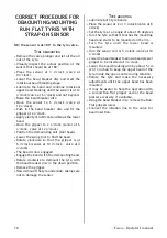
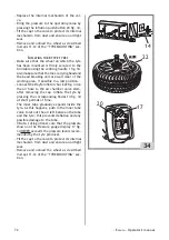
CORRECT PROCEDURE FOR
DEMOUNTING/MOUNTING
RUN FLAT TYRES FITTED
WITH VALVE SENSOR
NB: if the sensor is on the tyre valve.
d
emounting
• Remove the valve plunger and let all the air
out of the tyre.
• NB: If necessary, remove the valve fixing nut
and let the sensor to fall into the tyre.
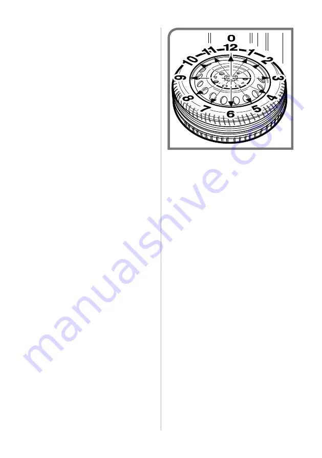
• Place the sensor at 3 o’clock.
• Lower the bead breaker disc and start the
rotational bead breaking stage.
• Lubricate the bead and continue rotational
upper bead breaking until the sensor is at 12
o’clock and not beyond.
• Raise the bead breaker disc.
• Move the sensor to 6 o’clock.
• Push in the bead breaker disc and fit the
gripper at 2 o’clock.
• Apply plenty of lubricant and break the lower
bead.
• Move the gripper to 2 o’clock (sensor at 6
o'clock).
• Position the demounting unit (tool head).
• Lower the swing tool to find the bead.
• Rotate clockwise so that the gripper is at 6
o’clock (sensor at 10 o’clock).
• The bead is now engaged.
• Engage the bead with the demounting head.
• Rotate clockwise to demount the tyre, with
the bead breaker disc in the down position.
• Remove the gripper.
• Now demount the tyre underside, taking care
not to damage the sensor.
t
yre
mounting
• Refit the valve sensor (if removed).
• Lubricate both tyre beads.
• Place the sensor at 5 or 6 o’clock.
• Set the tyre at an angle of about 45 degrees
• Turn the tyre so that it touches the mounting
head and starts to be mounted on the rim.
• Rotate the tyre until the lower bead is
mounted.
• Turn the sensor to 4 or 5 o’clock.
• Lower the bead breaker to allow a bead presser
gripper to be inserted at 3 o’clock.
• Lower the bead breaking arm by about 5 cm
(2 or 3 inches) to keep the upper bead of the
tyre inside the open centre during rotation.
• Rotate the tyre and make the necessary
adjustments until the upper bead has been
mounted.
• It may be useful to help the operation with
a second Run-Flat gripper and/or the bead
presser accessory, if available.
• Using the bead breaker disc, remove the Run-
Flat grippers used.
• Connect the inflation line to the valve for
bead insertion.
Содержание AQUILA RAPTOR
Страница 34: ...34 Italiano Manuale d uso 35 a b c e d ...
Страница 39: ... Italiano Manuale d uso 39 4 104805A ...
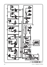
Страница 40: ...40 Italiano Manuale d uso 4 108818 ...
Страница 41: ...41 ...
Страница 42: ...42 ...
Страница 74: ...74 English Operator s manual 35 a b c e d ...
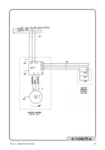
Страница 79: ... English Operator s manual 79 4 104805A ...
Страница 80: ...80 English Operator s manual 4 108818 ...
Страница 81: ...81 ...
Страница 82: ...82 ...
Страница 114: ...114 Français Manuel d utilisation 35 a b c e d ...
Страница 119: ... Français Manuel d utilisation 119 4 104805A ...
Страница 120: ...120 Français Manuel d utilisation 4 108818 ...
Страница 121: ...121 ...
Страница 122: ...122 ...
Страница 134: ...134 Deutsch Betriebsanleitung 15 1 12 13 2931 14 2 18 3 8 9 5 28 6 30 7 10 11 4 17 27 25 26 23 20 24 22 21 30 C B A 10 ...
Страница 154: ...136 Deutsch Betriebsanleitung 35 a b c e d ...
Страница 159: ... Deutsch Betriebsanleitung 123 4 104805A ...
Страница 160: ...134 Deutsch Betriebsanleitung 4 108818 ...
Страница 161: ......
Страница 162: ...162 ...
Страница 174: ...174 Español Manual de uso 15 1 12 13 2931 14 2 18 3 8 9 5 28 6 30 7 10 11 4 17 27 25 26 23 20 24 22 21 30 C B A 10 ...
Страница 194: ...176 Español Manual de uso 35 a b c e d ...
Страница 199: ... Español Manual de uso 199 4 104805A ...
Страница 200: ...174 Español Manual de uso 4 108818 ...
Страница 204: ...204 ...
Страница 205: ...205 ...

