background image

- I

talIano

 -

 Manuale d’uso  

39

4-104805A

Содержание AQUILA RAPTOR

Страница 1: ...33A 05 2012 Manuale d uso Operator s manual Manuel d utilisation Betriebsanleitung Manual de uso Automotive Equipment Service co inc 1022 Industrial court Suite b Lexington SC 29072 803 951 3718 www aescosc com info aescosc com ...

Страница 2: ...e reproduction et d adaptation totale ou partielle par n importe quel moyen y compris microfilms et copies photostatiques sont réservés Les informations contenues dans ce manuel sont sujettes à des variations sans préavis Alle Rechte der Übersetzung elektronischen Speicherung Vervielfältigung und Teil oder Gesamtanpassung unter VerwendungvonMittelnjedwederArt einschließlichMikrofilm und fotostatis...

Страница 3: ...GLI PRATICI RACCOMANDAZIONI ED INFORMAZIONI IMPORTANTI 17 GUIDA ALL UTILIZZO CORRETTO DELLA MACCHINA 18 SMONTAGGIO 18 MONTAGGIO 25 PROCEDURA OMOLOGATA DI SMONTAGGIO E MONTAGGIO PNEUMATICI UHP E RUN FLAT 28 PROCEDURA STRAORDINARIA DI MONTAGGIO 28 PROCEDURA CORRETTA PER SMONTAGGIO MONTAGGIO PNEUMATICO RUN FLAT CON SENSORE A VALVOLA 29 PROCEDURA CORRETTA PER SMONTAGGIO MONTAGGIO PNEUMATICO RUN FLAT C...

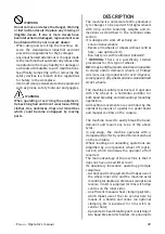
Страница 4: ...Attenersi a quanto descritto in questo ma nuale eventualiusidell apparecchiaturanon espressamente descritti sono da ritenersi di totale responsabilità dell operatore ATTENZIONE Per operare correttamente con questa mac china occorre essere un operatore qualificato e autorizzato in grado di capire le istruzioni scrittedatedalproduttoredellamacchina dei pneumatici e dei cerchi essere addestrato e con...

Страница 5: ...sbal latura montaggio sollevamentoeinstallazione di seguito descritte Conservare gli imballi originali per eventuali trasporti futuri L inosservanza di tali raccomandazioni può provocare danneggiamenti alla macchina e pregiudicare la sicurezza dell operatore Liberare la macchina dalla parte superiore dell imballo Lamacchinaècompletamentemontata ècom posta da due gruppi principali 2 la macchina 3 l...

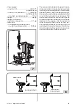
Страница 6: ...iene eseguita in un luogo aperto è necessario che la macchina sia pro tetta da una tettoia ATTENZIONE Il pavimento deve essere in grado di reggere un carico pari alla somma del peso proprio dell apparecchiatura e del carico massimo ammesso tenendo conto della base di ap poggio al pavimento e degli eventuali mezzi di fissaggio previsti Portare lo smontagomme nella posizione di lavorodesiderata risp...

Страница 7: ...are sul cavo di alimentazione una spina conforme alle normative vigenti collegarelamacchinaadunapropriaconnes sioneelettrica Afig 5 dotatadiunapposito interuttore automatico differenziale con sensibilità 30mA A B 5 montare dei fusibili di protezione della linea di alimentazione dimensionati secondo le indicazioni riportate nello schema elettrico generale contenuto nel presente manuale predisporre ...

Страница 8: ...IONE L inosservanza delle istruzioni e delle avver tenze di pericolo può provocare gravi lesioni agli operatori e ai presenti Non mettere in funzione la macchina prima di aver letto e compresotuttelesegnalazionidipericolo at tenzione e avvertenza di questo manuale Per operare correttamente con questa mac china occorre essere un operatore qualificato e autorizzato in grado di capire le istruzioni s...

Страница 9: ... runflat a fianco rinforzato ATTENZIONE Per questi sistemi di ruote sono state specificatamente studiate procedure dedicate N B Si possono incontrare difficoltà oggettive e a volte proibitive di bloccaggio e o di smon taggio su ruote appartenenti al settore Auto d epoca fuori produzione da oltre 30 anni alcune tipologie di ruote da Rally ed auto non omologate per uso stradale Di costruzione solida...

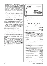
Страница 10: ... sono riportati elementi di identificazione della stessa ed alcuni dati tecnici In particolare oltre agli estremi del costruttore sono riportati Mod Modello della macchina V tensione di alimentazione in Volt A Corrente assorbita in Ampere kW Potenza assorbita in kW Hz Frequenza in Hz Ph Numero delle fasi bar Pressione di esercizio in bar Serial N il numero di matricola della macchina ISO 9001 Atte...

Страница 11: ...o livelli di emissioneenonrappresentanonecessariamente livelli operativi sicuri Nonostante esista una relazione fra livelli di emissione e livelli di esposizione questa non può essere utilizzata in modo affidabile per stabilire se siano ne cessarie o meno ulteriori precauzioni I fattori che determinano il livello di esposizione a cui è soggetto l operatore comprendono la durata dell esposizione le...

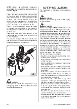
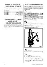
Страница 12: ...umatici uti lizzandoglistrumentidicuisonodotatisecondo quanto descritto in questo manuale ATTENZIONE Ognialtroutilizzodiversodaquellodescrittoè da considerarsi improprio ed irragionevole Le macchine sono dotate di un sistema di gon fiaggio indipendente dalle altre funzioni sopra descritte Prestare molta attenzione nel suo utilizzo leggere il capitolo GONFIAGGIO ATTENZIONE Durante il lavoro è scons...

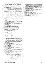
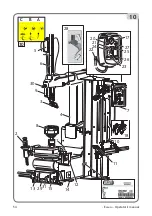
Страница 13: ...otazione 17 Manometro per lettura pressione di gonfiag gio 18 Gruppo filtro Regolatore Lubrificatore gruppo che permette di regolare filtrare deumidificare e lubrificare l aria di alimen tazione 19 Targhetta di identificazione 20 Pulsante di sgonfiaggio 21 Valvola comando salita discesa braccio stallonatore superiore 22 Raccordo Doyfe 23 Valvola comando salita discesa braccio stallonatore inferior...

Страница 14: ...14 Italiano Manuale d uso 15 1 12 13 2931 14 2 18 3 8 9 5 28 6 30 7 10 11 4 17 27 25 26 23 20 24 22 21 30 C B A 10 ...

Страница 15: ...o stallonatore hanno una apertura laterale MAI sostare dietro la macchina Pericolo di schiacciamento Non inserire mai nessuna parte del corpo ed in particolarelemani tral utensiledismontaggio montaggio e la ruota Controlli preliminari Verificare sul manometro del gruppo filtro Regolatore Lubrificatore la presenza di una pressione minima di 8 bar Verificare che l allacciamento della macchina alla r...

Страница 16: ...atico Ilcerchioe olopneu maticopossonosubireinavvertitamentedelle lesioni generando un rischio di esplosione di quest ultimo nella fase di gonfiaggio Ruote europee ad alte prestazioni curvatura asimmetrica fig 11 C alcune ruote europee presentano cerchi con curvature molto accen tuate C eccetto in corrispondenza del foro della valvola A sul quale lato la curvatura è più leggera B Su queste ruote l...

Страница 17: ...ed il bordo cerchio questo consentirà una rapida salita del tallone sul cerchio consentendone lo smontaggio fig 12 12 Se durante la fase iniziale di smontaggio l utensilenonriescearibaltarecompletamente il tallone dello pneumatico può essere che lo pneumatico sia ancora intallonato a 180 rispetto la zona preposta per lo smontaggio In quel caso è indispensabile ripristinare la condizione ottimale c...

Страница 18: ...contattoavvienecon un carico limitatissimo Se si vuole evitare di sentire il rumore è sufficiente in fase di carico tallone comprimere lo stesso maggiormente con il disco stallonatore ATTENZIONE L operazione di stallonatura è un azione no toriamente pericolosa Tale operazione deve essere eseguita secondo le indicazioni sotto riportate Ruote per autovettura fuoristrada e veicoli commerciali leggeri...

Страница 19: ...re il cono idoneo per il foro del cerchio premere il pedale 31 Inserire il dispositivo di bloccaggio nel foro centrale della ruota Fig 15 assicurarsi che ci sia un buon centraggio tra cono e cercchio rilasciare il pedale 31 15 3 Sgonfiaggio pneumatico fig 16 Sgonfiare completamente lo pneumatico agendo sulla valvola 16 4 Posizionamento stallonatore fig 17 17a Portare il gruppo stallonatore dalla p...

Страница 20: ...chio ed il disco stallonatore di 2 3 mm azionare il comando 24 per bloccare lo spostamento orizzontale NOTA CON QUESTO COMANDO SI OTTIENE IL BLOCCAGGIO SIMULTANEO DI ENTRAMBI I BRACCI QUINDI IL BRACCIO INFERIORE E GIA PRONTO PERAL STALLONATURAE LAPOSIZIO NE RESTERA MEMORIZZATAFINOAQUANDO IL COMANDO 24 NON VERRA SBLOCCATO 17 17a 2 3mm ...

Страница 21: ...l cerchio durante la rotazione Riportare con il comando 21 il braccio superiore verso l alto sopra la ruota 18 6 Stallonatura inferiore fig 19 Precaricare il disco stallonatore azionando il comando 23 è consigliata una precarica con schiacciamento dello pneumatico di 5mm circa Azionare la penetrazione del disco comando 26 e successivamente avviare la rotazione della ruota comando a pedale 15 conte...

Страница 22: ... tallone superiore fig 21 A B C Con il disco stallonatore superiore creare lo spazio sufficiente tra cerchio e copertura per consentire l operazione di basculamento utensile smontaggio Azionare comando 28 per effettuare l opera zione di basculamento utensile smontaggio A B C Per facilitare l operazione di aggancio tallone è importante compiere una piccola rotazione dell autocentrante Per facilitar...

Страница 23: ...utilizzo del disco stallonatore agendo sulla parte inferiore del pneumatico Durante l operazione di smontaggio qualora il pneumatico tendesse a scivolare sul bordo del cerchio si può utilizzare l HELP fornito in dotazione vedi capitolo CONSIGLI PRATICI RACCOMANDAZIONI ED INFORMAZIONI UTI LI 22 10 Smontaggio del tallone inferiore fig 23 Smontaggio con utilizzo della torretta porta utensile Posizion...

Страница 24: ...15 e contemporaneamente alzare a colpetti co mando 23 il disco Ruotare fino al completo smontaggio del pneumatico 24 A B C D 11a Smontaggio del tallone inferiore Per i cerchi con canale posto sul lato interno può essere necessario utilizzare il braccio stallonatoresuperiorecongruppostallonatore ruotato di 180 12 Smontaggio completato A smontaggio completato riportare il braccio inferioretuttoinbas...

Страница 25: ... complesso tubeless AVVERTENZA Verificare sempre il giusto accoppiamento co pertura cerchio in termini di compatibilità co pertura tubeless su cerchio tubeless copertura tube type su cerchio tube type e di dimensioni geometriche diametro di calettamento lar ghezza di sezione Off Set e tipo di profilo della balconata prima del loro assemblaggio Verificare inoltre che i cerchi non abbiano subito def...

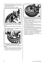
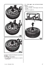
Страница 26: ...io e creare lo spazio per l introduzione del morsetto 28 7 Montaggio tallone superiore fig 29 29a Montare il morsetto nello spazio creato dal disco stallonatore fig 28 Avviare la rotazione pedale15 per montare il tallone fino a quando il morsetto si trova in prossimità dell utensile Per ruote di grandi dimensioni oltre 19 o particolarmentedurepuòessereutilel utilizzo di un secondo morsetto Esercit...

Страница 27: ...natore in posizione di riposo 9 Gonfiaggio pneumatico Per il gonfiaggio fare riferimento al capitolo GONFIAGGIO 10 Sbloccaggio ruota dall autocentrante fig 30 Premere il pedale 31 Sfilare la maniglia di bloccaggio dalla ruota Fig 30 Rilasciare il pedale 31 31 30 ...

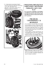
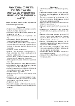
Страница 28: ...eumatico PROCEDURA STRAORDINARIA DI MONTAGGIO Una variazione alla procedura di montaggio sopra spiegata può essere effettuata in pre senza di cerchi con canale molto ridotto se non proprio inestistente fig 11 B In questi eccezionalicasilaproceduradimontaggiopuò essere agevolata adottando una variante alla normale procedura Il primo tallone si monta normalmente Per il montaggio del secondo tallone ...

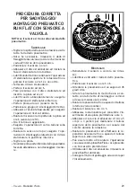
Страница 29: ...ione di carico tallone sulla torretta Ruotare in senso orario per eseguire l ope razione di smontaggio aiutandosi con il disco stallonatore in posizione inferiore Togliere la pinza Smontare poi la parte inferiore dello pneumatico facendo attenzione a non danneggiare il senso re Montaggio Reinstallare il sensore a valvola se rimos so Lubrificare entrambi i talloni dello pneuma tico Posizionare il s...

Страница 30: ...to Eseguire l operazione di carico tallone sulla torretta Ruotare in senso orario per eseguire l ope razione di smontaggio aiutandosi con il disco stallonatore in posizione inferiore Togliere la pinza Smontare poi la parte inferiore dello pneuma tico facendo attenzione a non danneggiare il sensore Montaggio Lubrificare entrambi i talloni dello pneuma tico Posizionare il sensore a ore 2 o 3 valvola...

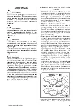
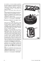
Страница 31: ...ruota sulla quale è stata montata la copertura sia saldamente bloccata all autocentrante mediante il dispositivo di bloccaggio 1 fig 34 Assicurarsi inoltre che la torrettaportautensiliedilgruppostallonatore siano lontani dalla zona di lavoro possibil mente in posizione di riposo Fissare al cerchio una nuova valvola Collegare il raccordo Doyfe del tubo di gonfiaggio 22 fig 34 allo stelo della valvo...

Страница 32: ...ilgruppostallonatore siano lontani dalla zona di lavoro possibil mente in posizione di riposo Collegare il raccordo Doyfe del tubo di gonfiaggio 22 fig 34 allo stelo della valvola della camera d aria dopo avere rimosso il cappellotto Gonfiareilpneumaticopremendo a brevi intervalli il relativo Pedale 14 fig 34 La camera d aria si espande gradualmente all interno della copertura Durante tale fase ag...

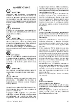
Страница 33: ...sciutto Evitare il contatto con solventi AVVERTENZA Tenere pulita la zona di lavoro Non usare mai aria compressa getti d acqua o diluente per rimuovere sporcizia o residui dalla macchina Nei lavori di pulizia operare in modo da im pedire quando ciò sia possibile il formarsi o il sollevarsi della polvere MANUTENZIONE AVVERTENZA il libretto Pezzi di ricambio non autorizza l utente ad intervenire sul...

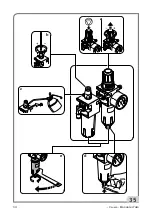
Страница 34: ...34 Italiano Manuale d uso 35 a b c e d ...

Страница 35: ...ali felpati internamente occhiali in caso di schizzi INFORMAZIONI AMBIENTALI La seguente procedura di smaltimento deve essere applicata esclusivamente alle macchi ne in cui la targhetta dati macchina riporta il simbolo del bidone barrato Questo prodotto può contenere sostanze che possono essere dannose per l ambiente e per la salute umana se non viene smaltito in modo opportuno Vi forniamo pertant...

Страница 36: ...se c è un tubo piegato Verificare funzionamento valvola salita e discesa Gruppo stallonatore ha poca forza non stallona e perde aria Eseguireleverifichedelpuntosopra Gruppo stallonatore non funziona Guarnizioni cilindro logore Sostituire guarnizioni Sostituire cilindro stallonatore grembiuli resistenti agli oli minerali schermi protettivi in caso di schizzi Olio minerale indicazioni di pronto socc...

Страница 37: ...nto Cilindro stallonatore perde aria dal perno Guarnizioni di tenuta logore Sostituire guarnizioni Sostituire cilindro stallonatore Riduttore rumoroso L autocentrante fa 1 3 di giro poi si blocca Riduttore sta grippando Sostituire riduttore L autocentrante non blocca i cerchi Gruppo innesto maniglia difettoso Verificare che sia fasata bene Sostituire la piastrina nell autocentrante Verificare che ...

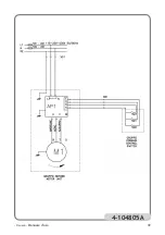
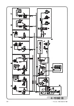
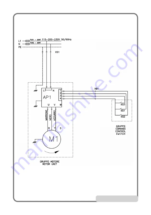
Страница 38: ...velocità SQ2 Microinterruttore rotazione senso ORA RIO SQ3 Microinterruttore rotazione senso AN TIORARIO XB1 Connettore SCHEMA PNEUMATICO Tavola cod 4 108818 A B COMANDO CILINDRO STALLONATORE E CILINDRO PENETRAZIONE DISCO STALLONA TORE SUPERIORE E INFERIORE 1 Cilindro stallonatore 2 Valvola 5 3 NC 3 Filtro silenziatore 4 Valvola 3 2 NA 5 Cilindro penetrazione C COMANDO BLOCCAGGIO STALLONATORE 6 Va...

Страница 39: ... Italiano Manuale d uso 39 4 104805A ...

Страница 40: ...40 Italiano Manuale d uso 4 108818 ...

Страница 41: ...41 ...

Страница 42: ...42 ...

Страница 43: ...2 MAIN OPERATING PARTS 53 PRACTICAL HINTS ADVICE AND USEFUL INFORMATION 57 GUIDE TO THE CORRECT USE OF THE MACHINE 58 TYRE DEMOUNTING 58 TYRE MOUNTING 65 APPROVED M D PROCEDURE FOR UHP AND RUN FLAT TYRES 68 EXTRAORDINARY MOUNTING PROCEDURE 68 CORRECT PROCEDURE FOR DEMOUNTING MOUNTING RUN FLAT TYRES FITTED WITH VALVE SENSOR 69 CORRECT PROCEDURE FOR DEMOUNTING MOUNTING RUN FLAT TYRES WITH STRAP ON S...

Страница 44: ...ducer declines all liability in the case of usesofthemachinenotspecificallydescribed and authorised in this manual WARNING This machine must be used only by qualified andauthorisedpersonnel Aqualifiedoperator is construed as a person who has read and understood the tyre changer manufacturer s instructions as well as the tyres and wheel rims manufacturers is suitably trained and is conversant with ...

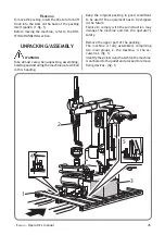
Страница 45: ...lling the machine as described in this heading Keep the original packing in good conditions to be used if the equipment has to be shipped in the future Failure to comply with these instruction may damage the machine and risk the operator s safety Remove the upper part of the packing The machine is fully assembled comprising two main groups 2 the machine 3 the ac cessories fig 1 Identify the points...

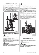
Страница 46: ...is installed outdoors it must be properly sheltered under a roof WARNING The floor must be able to withstand a load equal to the sum of the weight of the equip mentitselfandthemaximumpayload bearing inmindthesupportsurfaceareaandeventual anchor fixtures used Install the tyre changer in the chosen work po sition complying with the minimum clearances shown in fig 3 The machine must be placed on a ho...

Страница 47: ...st fit a power plug on the power supply lead in compliance with the relevant safety standards connect the machine to its own electrical connection A fig 5 and fit a differential safety circuit breaker with 30 mA residual current A B 5 fit fuses to protect the power supply line rated as indicated on the general wiring diagram in this manual installanefficientearthingcircuittoprotect the workshop el...

Страница 48: ...t operate the machine until you have read and understood all the danger warning and caution notices in this manual This machine must be used only by qualified and authorised personnel A qualified operator is construed as a person who has read and understood the manufacturer s instructions is suitably trained and is conversant with safety and adjustment procedures to be adhered to during operations...

Страница 49: ...idewalls WARNING There are specifically studied procedures for this type of wheels NB Itmaybedifficultandsometimesimpossible to clamp and or demount wheels of Vintage cars cars out of production for over 30 years sometypesofrallywheelsandnon standardised street wheels The machine is solidly constructed It operates with the wheel in a horizontal position for both bead breaking and demounting mounti...

Страница 50: ...damage to rim and tyre Each machine carries a plate with its identifi cation data and some technical data As well as the manufacturer s details it in dicates Mod Machinemodel V powersupplyvoltage in Volts A Input voltage in Amperes kW Absorbed power in kW Hz Frequency in Hz Ph Numberofphases bar Operatingpressure in bar Serial No Machine serial number ISO 9001 Certification of the company s Qualit...

Страница 51: ...se levels indicated correspond to emis sionlevelsanddonotnecessarilyrepresentsafe operatinglevels Althoughthereisarelationship between emission levels and exposure levels thiscannotbeusedreliablytoestablishwhether or not further precautions are necessary The factors which determine the level of exposure to which the operator is subject to include the duration of the exposure the characteristics of...

Страница 52: ...nt and demount tyres using the tools with which it is equipped following the instructions in this manual WARNING Any other operations carried out on the machine are considered as improper use and shall be construed as negligence These machines are equipped with an inflation system independent from any other function described above Take great care when using it read the INFLATION chapter WARNING Y...

Страница 53: ...n pressure 18 Filter Regulator Lubricator Unit regulates pressure filters removes humidity of and lubricates the compressed air supplied 19 Data plate 20 Deflation push button 21 Control valve for upper bead breaking arm ascent descent 22 Doyfe inflator chuck 23 Control valve for lower bead breaking arm ascent descent 24 Control valve for locking dual position bead breaker supports 25 Control push...

Страница 54: ...54 English Operator s manual 15 1 12 13 2931 14 2 18 3 8 9 5 28 6 30 7 10 11 4 17 27 25 26 23 20 24 22 21 30 C B A 10 ...

Страница 55: ...holder arm and the bead breaking unit have a lateral opening NEVER stand behind the ma chine Risk of crushing Never place any part of the body particularly yourhands betweenthedemounting mounting tool and the wheel Preliminary checks Check that there is a pressure of at least 8 bar on the pressure gauge of the Filter Regulator Lubricator unit Check that the machine has been adequately connected to...

Страница 56: ...ion when mounting the tyre The rim and or the tyre may be damaged ac cidentally with the risk of the tyre exploding during the inflation stage European style high performance wheels asymmetric curvature fig 11 C some Eu ropean wheels have rims with very pronounced curvature C except in the area of the valve hole A where the curvature is less pronounced B On these wheels the bead must first be brok...

Страница 57: ...ge of the rim This will help lifting the bead quickly off the rim so that it can be demounted fig 12 12 Upon demounting if the tool cannot comple telyoverturnthetyrebeadtoallowdemounting to start the tyre bead may still be or just have been inserted at 180 to the demounting zone In this case it is essential to restore the ideal condition withthetyrebeadinsidethewellof the rim This operation can be...

Страница 58: ... simplypressthebeadbreakerdischarder against the bead when picking it up WARNING Bead breaking is well known to be a dangerous operation It must be carried out in accordance with the instructions below Wheel for cars off road and light commercial vehicles GUIDE TO THE CORRECT USE OF THE MACHINE WARNING Read the PRACTICAL HINTS ADVICE AND USEFUL INFORMATION section above with great care TYRE DEMOUN...

Страница 59: ...e the correct cone for the hole of the rim Press the clamping pedal 31 Put the clamping device in the drop centre of the wheel Fig 15 Make sure the cone and the rim are perfectly centred Release the pedal 31 15 3 Tyre deflation fig 16 Operate the valve and fully deflate the tyre 16 4 Bead breaker positioning fig 17 17a Move the bead breaking unit from the its rest to its operating position Move th...

Страница 60: ...of the rim and the bead breaker disc operate the control 24 to inhibit any further horizontal movement NB SIMULTANEOUS CLAMPING BY BOTH ARMS IS ACHIEVED THROUGH THIS CONTROL THE REFORE THE LOWERARM IS READY FOR BEAD BREAKING ANDTHISPOSITIONWILLBESTORED IN THE MACHINE MEMORY UNTIL CONTROL 24 IS UNLOCKED 17 17a 2 3mm ...

Страница 61: ...breakthebead Therimbeadshouldbegreased during the spin Set the upper arm upwards over the wheel with control 21 18 6 Lower bead breaking fig 19 Preload the bead breaker disc using control 23 a tyre crushing preload of about 5 mm is advisable Activate disc penetration control 26 and then start wheel spinning pedal control 15 while lowering the bead breaker disc a little at a time control 23 Perform...

Страница 62: ...ock 9 to fix the tool 3 position G 20 9 28 8 Upper tyre bead coupling fig 21 A B C Create enough space between the rim and the tyre with the bead breaker disc to allow the demounting tool to tilt Operate control 28 for demount tool A B C tilting It is important to rotate the turntable slightly to facilitate engagement of the bead For easier bead coupling it might be very helpful to use the bead br...

Страница 63: ... the bead is completely demounted Here again it might be helpful to use the bead breaker disc on the lower part of the tyre Upon demounting if the tyre tends to slip on the rim edge the HELPaccessory supplied can be used see PRACTICAL HINTS ADVICE AND USEFUL INFORMATION 22 10 Lower bead demounting fig 23 Using tool carrying head Place the tool on the edge of the rim A Push the bead breaker disc ag...

Страница 64: ...d at the same time raise the disc by tapping on con trol 23 Rotate until the tyre is completely demounted 24 A B C D 11a Lower bead demounting It might be necessary to use the upper bead breaking arm with the bead breaking unit rotated by 180 for rims with an internal drop centre 12 Demounting complete Once demounting is finished set the lower arm totally downwards control 23 unlock the bead break...

Страница 65: ...N Always check that the tyre rim combination is correct in terms of compatibility tubeless tyre on tubeless rim tube type tyre on tube type rim and geometrical size keying diame ter cross section width Off Set and shoulder profile before mounting Also check that rims are not deformed that their fixing holes have not become oval that they are not scaled or rusty and that they do not have sharp burr...

Страница 66: ...ake enough room for the clamp to be inserted 28 7 Upper bead mounting fig 29 29a Mount the clamp in the space created by the bead breaker disc fig 28 Spin the wheel pedal 15 to mount the bead until the clamp is close to the tool For large over 19 or particularly difficult wheels a second clamp may be useful Apply further pressure to the tyre control 21 and move the tool head to its rest position c...

Страница 67: ... the bead breaking unit to the rest position 9 Tyre inflation For inflation see INFLATION section 10 Unclamping the wheel from the turnta ble fig 30 Press the pedal 31 Pull the clamping device out of the wheel Fig 30 Release the pedal 31 31 30 ...

Страница 68: ... the Tyre Industry EXTRAORDINARY MOUNTING PROCEDURE Avariation of the mounting procedure explai ned above may be adopted in case of rims with very small or non existent drop centre fig 11 B In these exceptional cases the mounting procedure can be facilitated by using a variant of the normal procedure The first bead is mounted in the usual way To mount the second bead position the movable tool as w...

Страница 69: ...e bead is now engaged Engage the bead with the demounting head Rotate clockwise to demount the tyre with the bead breaker disc in the down position Remove the gripper Now demount the tyre underside taking care not to damage the sensor Tyre mounting Refit the valve sensor if removed Lubricate both tyre beads Place the sensor at 5 or 6 o clock Set the tyre at an angle of about 45 degrees Turn the ty...

Страница 70: ...lock sensor at 10 o clock valve at 4 o clock The bead is now engaged Engage the bead with the demounting head Rotate clockwise to demount the tyre with the bead breaker disc in the down position Remove the gripper Now demount the tyre underside taking care not to damage the sensor Tyre mounting Lubricate both tyre beads Place the sensor at 2 or 3 o clock valve at 8 o clock Set the tyre at an angle...

Страница 71: ...e clamping device 1 fig 34 Alsomakesurethatthetool carryingheadand the bead breaking unit are well clear of the working area if possible in a rest position Fix a new valve to the rim Connect the Doyfe inflator chuck 22 fig 34 on the air hose to the valve stem after removing the cap Inflate the tyre by pressing Pedal 14 fig 34 The tyre expands and the beads seat Continue inflating up to the maximum...

Страница 72: ...rea if possible in a rest position Connect the Doyfe inflator chuck 22 fig 34 on the air hose to the air chamber valve stem after removing the cap Inflate the tyre by pressing the corresponding Pedal 14 fig 34 at short periods of time The inner tube gradually expands inside the tyre As this happens push in the inner tube valve to let out the air left between the tube and the tyre this prevents def...

Страница 73: ...and out and thenturningit onceadjusted locktheknob again by pushing it back down fig 35a The lubricant flow rate is adjusted by turning the screw on the L element fig 35b the unit is normally pre calibrated at a pressure of 10 bar with lubricant having a viscosity of SAE20 so that one drop of lubricant which can be seen through the cover is released every 4 bead breaker cycles DANGER Before starti...

Страница 74: ...74 English Operator s manual 35 a b c e d ...

Страница 75: ...ed the same functions as the supplied equipment A disposal of the product different from what described above will be liable to the penalties prescribed by the national provisions in the country where the product is disposed of We also recommend you to adopt further mea sures for environment protection recycle the internalandexternalpackingoftheproductand properly dispose of dead batteries if cont...

Страница 76: ...f the applications of each type of extinguisher GLOSSARY Air delivery regulator Union allowing regu lation of the air flow Beading Operation which takes place during inflation and ensures perfect centring between the bead and the rim edge Bead breaking Operation in which the bead of the tyre is detached from the edge of the rim Bead pressing gripper A tool intended for use when mounting the top be...

Страница 77: ...r to minimise delays Bead breaker cylinder leaks air around the rod Air gaskets worn Replace gaskets Replace bead breaker cylinder Gear unit noisy The table top makes 1 3 of a spin and then stops Gear unit seizing Replace gear unit Table top fails to clamp rims Handle engagement unit faulty Check it is synchronised properly Replace the plate of the turntable Check there are no burrs Replace the lo...

Страница 78: ...wo speed micro switch SQ2 Micro switch CLOCKWISE rotation SQ3 Micro switch ANTICLOCKWISE rota tion XB1 Connector PNEUMATIC SYSTEM DIAGRAM Table code A B CONTROLFOR BEAD BREAKER CYLINDER AND PENETRATION CYLINDER FOR UPPERAND LOWER BEAD BREAKERS 1 Bead breaker cylinder 2 Valve 5 3 NC 3 Silencer filter 4 Valve 3 2 NO 5 Penetration cylinder C BEAD BREAKER LOCKING CONTROL 6 Valve 3 2 NC 7 Upper unlocki...

Страница 79: ... English Operator s manual 79 4 104805A ...

Страница 80: ...80 English Operator s manual 4 108818 ...

Страница 81: ...81 ...

Страница 82: ...82 ...

Страница 83: ... CONSEILS PRATIQUES RECOMMANDATIONS ET INFORMATIONS IMPORTANTES 97 GUIDE POUR L UTILISATION CORRECTE DE LA MACHINE 98 DEMONTAGE 98 MONTAGE 105 PROCÉDURE AGRÉÉE POUR LE MONTAGE ET DÉMONTAGE DES PNEUS UHP ET RUN FLAT 108 PROCEDURE EXTRAORDINAIRE DE MONTAGE 108 PROCEDURE CORRECTE POUR LE DEMONTAGE MONTAGE DU PNEU RUN FLAT AVEC CAPTEUR A SOUPAPE 109 PROCEDURE CORRECTE POUR LE DEMONTAGE MONTAGE DU PNEU...

Страница 84: ...l toute utilisation non prévue dans ce dernier est sous l entière responsabilité de l opérateur ATTENTION Pour travailler correctement avec cette machine il faut être un opérateur qualifié et autorisé capable de comprendre les in structions écrites données par le fabricant de l appareil des pneus et des jantes avoir reçu une formation et connaître les consignes de sécurité L utilisation de la mach...

Страница 85: ...rations de déballage montage levage et installation décrites Conserverlesemballagesd originepourd autres transports Le non respect de ces recommandations peut provoquerdesendommagementsàl appareilet compromettre la sécurité de l opérateur Libérer l appareil par la partie supérieure de l emballage L appareil est complètement monté il est composédedeuxgroupesprincipaux l appareil proprement dit 2 l ...

Страница 86: ...uvert l appareil doit être protégé par un abri ATTENTION Le sol doit être en mesure de supporter une chargeégaleàlasommedupoidsdel appareil et de la charge maximale admise en tenant compte de la base d appui au sol et des éven tuels moyens de fixation prévus Placer le démonte pneus dans la position de travail souhaitée en respectant les mesures minimales indiquées sur la fig 3 L appareildoitêtremo...

Страница 87: ...marche par rapport à la valeur nominale de la tension de plaque L utilisateur doit monter sur le câble d alimentation une fiche conforme aux normes en vigueur brancher l appareil à une connexion élec trique individuelle A fig 5 muni d un interrupteurautomatiquedifférentield une sensibilité de 30 mA A B 5 monter des fusibles de protection de la ligne d alimentation dimensionnés d après les indicati...

Страница 88: ...ements de danger peut entraîner de graves blessures aux opérateurs et aux per sonnesprésentes Nejamaisfairefonctionner l appareil avant d avoir lu et parfaitement compris toutes les signalisations de danger attention et avertissement se trouvant dans ce manuel Pour travailler correctement avec cet appareil il faut être un opérateur qualifié et autorisé en mesure de comprendre les instructions écri...

Страница 89: ...nterenverséeousansalésagecentral Utilisation du kit accessoire sur demande Pneus à flanc renforcé Attention Pour ces systèmes de roues des procédures spéciales ont été spécifiquement conçues N B On peut avoir des difficultés objectives et parfois prohibitives de blocage et ou de démontagesurdesrouesappartenantausecteur de Voiture d époque hors production depuis plus de 30 ans et certains types de ...

Страница 90: ... atteints Réduire l effort physique de l opérateur Garantir le bon état de la jante et du pneu Chaque appareil est muni d une plaque sur laquelle sont reportés les éléments d identi fication de cet appareil et quelques données techniques En particulier outre les données du fabricant sont indiqués Mod Modèle de l appareil V Tension d ali mentation en volts A Courant absorbé en ampères kW Puissance ...

Страница 91: ...quées sont des niveaux d émission et ne représentent pas forcément des niveaux opérationnels sûrs Bien qu il y ait une relation entre les niveaux d émission et les niveaux d exposition celle ci ne peut pas être utilisée de façon fiable pour établir si des précautions sont plus ou moins nécessaires Les facteurs qui déterminent le niveau d exposition auquel est assujetti l opérateur comprennent la d...

Страница 92: ...s instruments dont il est équipé selon ce qui est décrit dans ce manuel ATTENTION Toute autre utilisation différente de celle décrite doit être considérée impropre et déraisonnable Les appareils sont munis d un système de gon flage indépendant des autres fonctions décrites ci dessus Fairetrèsattentionlorsqu onl utilise lire le chapitre GONFLAGE ATTENTION Pendant le travail il est déconseillé d uti...

Страница 93: ...ion 17 Manomètre pour la lecture de la pression de gonflage 18 Groupe du filtre régulateur lubrificateur groupe qui permet de régler filtrer déshu midifier et lubrifier l air d alimentation 19 Plaquette d identification 20 Bouton de dégonflage 21 Soupape de commande de la montée et de la descente du bras détalonneur supérieur 22 Raccord Doyfe 23 Soupape de commande de la montée et de la descente d...

Страница 94: ...94 Français Manuel d utilisation 15 1 12 13 2931 14 2 18 3 8 9 5 28 6 30 7 10 11 4 17 27 25 26 23 20 24 22 21 30 C B A 10 ...

Страница 95: ...orte outil et le groupe détalonneur ont une ouverture latérale NE JAMAIS stationner derrière l appareil Danger d écrasement Ne jamais enfiler aucune partie du corps et surtout les mains entre l outil de démontage montage et la roue Contrôles préliminaires Vérifier sur le manomètre du groupe filtre régulateur lubrificateur la présence d une pression minimum de 8 bar Vérifier que le branchement de l...

Страница 96: ...e du pneu Lajanteet oulepneupeuventsubirpar inadvertance des blessures d où risque d ex plosion de ce dernier pendant le gonflage Roues européennes à hautes performances courbure asymétrique fig 11 C certaines roues européennes ont des jantes avec courbu res très accentuées C sauf en correspondance du trou de la soupape A sur le côté duquel la courbure est plus légère B Sur ces roues le détalonnag...

Страница 97: ...e bord de la jante cela permettra une montée rapide du talon sur la jante et son démontage fig 12 12 Pendant l opération de démontage si l outil n arrive pas à basculer complètement le talon dupneupourpouvoircommencerledémontage il se peut que le pneu soit encore ou de nouve au entalonné à 180 par rapport à la zone du démontage Dans ce cas il est indispensable derétablirlaconditionoptimalequiprévo...

Страница 98: ...contact aurait lieu avec une charge extrêmement limitée Si l on ne veut pas entendre le bruit lors du chargement du talon comprimer davantage ce dernier avec le disque détalonneur ATTENTION L opération de détalonnage est une action très dangereuse Cetteopérationdoitêtreeffectuée selon les indications reportées ci dessous Roues pour voiture tout terrain et véhicules utilitaires GUIDE POUR L UTILISA...

Страница 99: ...5 sélectionner le cône adapté au trou de la jante appuyer sur la pédale 31 introduire le dispositif de blocage dans le trou central de la roue fig 15 s assurer du bon centrage entre cône et jante relâcher la pédale 31 15 3 Dégonflage du pneu fig 16 Dégonfler complètement le pneu en agissant sur la soupape 16 4 Positionnement du détalonneur fig 17 17a Porter le groupe détalonneur de la position de ...

Страница 100: ...lée entre le bord de la jante et le disque détalonneur actionner la commande 24 pour bloquer le déplacement horizontal REMARQUE AVEC CETTE COMMANDE ON OB TIENTLEBLOCAGESIMULTANÉDESDEUXBRAS DONCLEBRASINFÉRIEURESTDÉJÀPRÊTPOUR LE DÉTALONNAGE ET LA POSITION RESTERA MÉMORISÉE JUSQU À CE QUE LA COMMANDE 24 NE SOIT PAS DÉBLOQUÉE 17 17a 2 3mm ...

Страница 101: ...le talon de la jante pendant la rotation Reporter avec la commande 21 le bras supérieur vers le haut sur la roue 18 6 Détalonnage inférieur fig 19 Précharger le disque détalonneur en action nant la commande 23 une précharge avec un écrasement du pneu de 5 mm environ est conseillée Actionnerlapénétrationdudisque commande 26 puis faire partir la rotation de la roue commande à pédale 15 simultanément...

Страница 102: ...rochage du talon supérieur fig 21 Avec le disque détalonneur supérieur créer l espacesuffisantentrelajanteetlaprotection pourpermettrel opérationdebasculementde l outil de démontage Actionnerlacommande28poureffectuerl opéra tion de basculement de l outil de démontage A B C Pourfaciliterl opérationd accrochedutalon il est important de faire tourner légèrement l autocentreur Pour faciliter l opérati...

Страница 103: ... phase le disque détalonneur pourrait être utile en agissant sur la partie inférieure du pneu Aucoursdudémontage silepneutendàglisser sur le bord de la jante on peut utiliser l AIDE fournie avec l équipement voir le chapitre CONSEILS PRATIQUES RECOMMANDATIONS ET INFORMATIONS UTILES 22 10 Démontage du talon inférieur fig 23 Démontage avec l utilisation de la tourelle porte outil Positionne l outil ...

Страница 104: ...imultanémentleverparà coups comman de 23 le disque Tourner jusqu au démontage complet du pneu 24 A B C D 11a Démontage du talon inférieur Pour les jantes avec creux placé sur le côté interne il peut être nécessaire d utiliser le bras détalonneur supérieur avec le groupe détalonneur tourné de 180 12 Démontage complété Une fois le démontage complété reporter le bras inférieur tout en bas commande 23...

Страница 105: ...la chambre à air dans l ensemble tube type et la soupape dans l ensemble Tubeless AVERTISSEMENT Vérifierlejusteaccouplementenveloppe jante en termes de compatibilité enveloppe Tubeless sur jante Tubeless enveloppe tube type sur jante tube type et de dimensions géométriques diamètre d assemblage largeur de section écart et type de profil du rebord avant leur assemblage Vérifier aussi que les jantes...

Страница 106: ...ace pour l introduction de l étau 28 7 Montage du talon supérieur fig 29 29a Monter l étau dans l espace créé par le disque détalonneur fig 28 Commencer la rotation pédale 15 pour mon ter le talon jusqu à ce que l étau se trouve à proximité de l outil Pour des roues de grandes dimensions plus de 19 ou particulièrement dures l utilisation d un second étau peut s avérer nécessaire Exercer une autre ...

Страница 107: ...ter le groupe détalonneur en position de repos 9 Gonflage du pneu Se reporter au chapitre GONFLAGE 10 Déblocage de la roue de l autocentreur fig 30 appuyer sur la pédale 31 extraire la poignée de blocage de la roue fig 30 relâcher la pédale 31 31 30 ...

Страница 108: ...rie des Pneus PROCEDURE EXTRAORDINAIRE DE MONTAGE Une variation de la procédure de montage expliquée ci dessus peut être effectuée en présence de jantes à creux très petit pour ne pas dire inexistant fig 11 B Dans ces cas exceptionnels la procédure de montage peut être facilitée en adoptant une variante à la procédure normale Le premier talon se monte normalement Pour lemontagedusecondtalon positi...

Страница 109: ...ur à 10 h Le talon est accroché Mettre le talon sur la tourelle Tourner en sens horaire pour effectuer l opération de démontage à l aide du disque détalonneur en position inférieure Retirer la pince Démonter ensuite la partie inférieure du pneu en veillant à ne pas endommager le capteur Montage Réinstaller le capteur à soupape s il avait été enlevé Lubrifier les deux talons du pneu Positionner le ...

Страница 110: ...à 6 h capteur à 10 h soupape à 4 h Le talon est accroché Mettre le talon sur la tourelle Tourner en sens horaire pour effectuer l opération de démontage à l aide du disque détalonneur en position inférieure Retirer la pince Puis démonter la partie inférieure du pneu en veillant à ne pas endommager le capteur Montage Lubrifier les deux talons du pneu Positionner le capteur à 2 ou 3 heures soupape à...

Страница 111: ...est solidement bloquée à l au tocentreur à l aide du dispositif de blocage 1 fig 34 Par ailleurs s assurer que la tourelle porte outils et le groupe détalonneur se trou vent éloignés de la zone de travail si possible en position de repos Fixer une nouvelle soupape à la jante Brancher le raccord Doyfe du tuyau de gon flage 22 fig 34 à la tige de la soupape après avoir enlevé le capuchon Gonfler le ...

Страница 112: ...ige de la soupape de la chambre à air après avoir enlevé le capuchon Gonfler le pneu en appuyant à courts intervalles sur la pédale 14 fig 34 La chambre à air s étend graduellement à l intérieur de l enveloppe Au cours de cette phase agir sur la soupape de la chambre à air en la poussant vers l intérieur afin de permettrel évacuationdel airquiresteentre la chambre et l enveloppe cela évite des gon...

Страница 113: ...oupeestpréréglésurune pressionde10barsavecunlubrifiantàviscosité SAE20 de façon à obtenir la distribution d une goutte de lubrifiant visible à travers la calotte prévue à cet effet tous les 4 actionnements du détalonneur DANGER Avant de procéder à toute opération d en tretien ou de ravitaillement de lubrifiant débrancher la machine de l alimentation pneumatique Contrôler à intervalles réguliers le...

Страница 114: ...114 Français Manuel d utilisation 35 a b c e d ...

Страница 115: ...areil votre distribu teur vous informera quant à la possibilité de rendre gratuitement un appareil obsolète de même type et servant aux mêmes fonctions L élimination non conforme aux consignes énoncées ci dessus est passible des sanctions prévues par la réglementation en matière de traitement des déchets en vigueur dans le pays où le produit est mis au rebut Nous vous invitons en outre à adopter d...

Страница 116: ...n l absence de moyens appropriés ou pour de petits incendies ATTENTION Les indications fournies sur ce tableau ont un caractère général et sont destinées à aider les utilisateurs Les possibilités d utilisation de chaque type d extincteur doivent être demandées au fabricant LEXIQUE Détalonnage Opérationquipermetdedécoller le talon du pneu du bord de la jante Entalonnage Opération effectuée lors du ...

Страница 117: ... ne fonctionnent pas De la poignée vanne de blocage l air ne passe pas Vérifier le parcours des tuyaux Remplacer la poignée soupape La potence ne s ouvre pas Vérin d ouverture de la potence défectueux Remplacer le vérin d ouverture de la poten ce L air n arrive pas au vérin Tuyaux pliés Remplacer la soupape Vérifier le serrage du pivot du bras Il y a une fuite d air sur les vérins de blocage du br...

Страница 118: ...itesse SQ2 Microcontact rotation sens HORAIRE SQ3 Microcontact rotation sens ANTI HORAIRE XB1 Connecteur SCHÉMA PNEUMATIQUE Tableau code 4 108818 A B COMMANDE DU VÉRIN DÉTALONNEUR ET DU VÉRIN DE PÉNÉTRATION DU DISQUE DÉTALONNEUR SUPÉRIEUR ET INFÉRIEUR 1 Vérin détalonneur 2 Soupape 5 3 NF 3 Filtre silencieux 4 Soupape 3 2 NO 5 Vérin de pénétration C COMMANDE DE BLOCAGE DU DÉTALON NEUR 6 Soupape 3 2...

Страница 119: ... Français Manuel d utilisation 119 4 104805A ...

Страница 120: ...120 Français Manuel d utilisation 4 108818 ...

Страница 121: ...121 ...

Страница 122: ...122 ...

Страница 123: ...CHE BETRIEBSELEMENTE 133 PRAKTISCHE HINWEISE EMPFEHLUNGEN UND WICHTIGE INFORMATIONEN 137 LEITFADEN FÜR DEN KORREKTEN EINSATZ DER MASCHINE 139 DEMONTAGE 139 MONTAGE 145 FREIGEGEBENE MONTAGE DEMONTAGEANLEITUNG FÜR UHP UND RUN FLAT REIFEN 148 AUSSERORDENTLICHE MONTAGEPROZEDUR 148 KORREKTE VORGEHENSWEISE ZUR DEMONTAGE MONTAGE VON RUN FLAT REIFEN MIT VENTIL DRUCKSENSOR 149 KORREKTE VORGEHENSWEISE ZUR D...

Страница 124: ...erlei Haftung beibestimmungsfremden nichtausdrücklich beschriebenen Einsätzen der Maschine ACHTUNG DerordnungsgemäßeBetriebderMaschineist ausschließlichdemzuständigenFachpersonal vorbehalten als solches muss man mit den Herstellervorschriften bezüglich des Maschi nenbetriebs der Reifen und Felgen vertraut sein diegeeigneteAusbildungdurchlaufenha ben unddiesicherheitstechnischenVorgaben für den Unf...

Страница 125: ...ckung zur Montage zum Anheben und zur Installation ist größte Vorsicht geboten Die Originalverpackung für künftige Transporte aufbewahren Die Missachtung dieser Anweisungen kann zu SchädenanderAusrüstungundzurGefährdungder Sicherheit des Bedienungspersonals führen Das Verpackungsoberteil aus Karton von der Maschine entfernen Die Maschine ist komplett montiert und besteht aus zwei Hauptgruppen 2 di...

Страница 126: ...NG Der Boden muss einer Last standhalten kön nen die der Summe des Eigengewichts der AusrüstungunddeszulässigenHöchstgewichts der Hebelast unter Berücksichtigung der am Boden aufliegenden Unterstruktur sowie der eventuellen vorgesehenen Befestigungsvor richtungen entspricht Die Reifenmontiermaschine in die gewünschte Arbeitsstellung bringen hierbei die Mindestab stände gemäß Abb 3 beachten Die Mas...

Страница 127: ...nwender muss folgende Eingriffe vorne hmen Am Netzkabel ist ein normgerechter Stecker anzubringen Die Maschine ist über einen werkseigenen Anschluss mit einem auf 30 mAAnsprechem pfindlichkeit eingestellten Fehlerstrom Leitungsschutzschalter an das Stromnetz anzuschließen A Abb 5 A B 5 Die Schmelzsicherungen der Netzleitung sind gemäß Stromlaufplan des vorliegenden Handbuchs auszulegen DieElektroa...

Страница 128: ...zuschwerenVerletzungenbei BenutzernundumstehendenPersonenführen Die Maschine darf erst nach sorgfältigem Lesen und eingehender Kenntnis aller Gefahren Warnhinweise des vorliegenden Handbuchs in Betrieb genommen werden Der ordnungsgemäße Betrieb der Maschine ist ausschließlich dem zuständigen Fachpersonal vorbehalten Als solches muss man mit den Herstellervorschriften vertraut sein die geei gnete A...

Страница 129: ...g des Zubehör Sets auf Anfrage Run In Flatreifen mit verstärkter Seite Achtung FürdieseReifensystemewurdenextra entsprechende Arbeitsverfahren studiert Zur Beachtung Bezüglich der Einspannung und oder Demontage von Oldtimer Rädern seit mehr als 30 Jahren außer Produktion undeinigenRallye Räder TypenundRädernvon Fahrzeugen die nicht für den Straßenverkehr zugelassensind könnenobjektiveundmitunter u...

Страница 130: ...rperlichen Einsatzes des Anwenders Schonende Handhabung der Felge und des Reifens Jede Maschine ist mit einem Typenschild ver sehen auf der die Informationen für deren Identifikation und einige technische Daten angegeben sind Neben den Kenndaten des Herstellers weist das Schild folgende Angaben auf Mod Maschinenmodell V Versorgungs spannung in Volt A Aufgenommener Strom in Ampere kW Leistungsaufna...

Страница 131: ... um Emissionswerte die nicht unbedingt sichere Betriebsgeräuschpegel wiedergeben Trotz der Beziehung zwischen den vorliegenden Emissionspegeln und den Geräuschpegeln denen dieAnwenderausgesetztsind könnendieAngaben nicht zuverlässig für die Bestimmung der Ergrei fung weiterer Schutzmaßnahmen herangezogen werden Zu den Faktoren für die Bestimmung des Geräuschpegels demderAnwenderausgesetztist zähle...

Страница 132: ...ausgestattet ist und unter Beachtung der im vorliegendenHandbuchenthaltenenAnweisungen konzipiert ACHTUNG Jeder andere Einsatz gilt als unsachgemäß und unverantwortlich Das eingebaute Füllsystem der Maschinen ar beitet unabhängig zu den oben beschriebenen Maschinenfunktionen EsistdeshalbmitVorsicht anzuwenden siehe Kapitel REIFENFÜLLEN ACHTUNG Esempfiehltsich ausschließlichmitOriginalaus rüstungen...

Страница 133: ...rrichtung 11 Abdrückscheibe 12 Fettbehälter 13 Pedal für das Abkippen der Montagesäule 14 Reifenbefüllpedal 15 Drehpedal 17 Druckmesser für das Ablesen des Reifendrucks 18 Filter Regel Schmiersystem Gruppe Vor richtung für die Regelung Filterung das Entfeuchten und Schmieren der Versorgungs druckluft 19 Typenschild 20 Luftablasstaste 21 Steuerventil für den Anstieg Abstieg des oberen Abdrückarms 2...

Страница 134: ...134 Deutsch Betriebsanleitung 15 1 12 13 2931 14 2 18 3 8 9 5 28 6 30 7 10 11 4 17 27 25 26 23 20 24 22 21 30 C B A 10 ...

Страница 135: ... Abbdrückvorrichung öffnen sich zur Seite DerAufenthalthinterderMaschine ist STRENGSTENS verboten Quetschgefahr Darauf achten dass kein Körperteil insbe sondere die Hände niemals zwischen das Demontage Montagewerkzeug und das Rad gelangt Vorüberprüfungen AmManometerderFilter Regel Schmiersystem Gruppeüberprüfen obeinDruckvonmindestens 8 bar anliegt Überprüfen ob der Anschluss der Maschine an das S...

Страница 136: ...hen Die Felge und oder der Reifen können ohne Vorwarnung geschädigt werden wodurch die Gefahr des Reifenber stens in der Füllphase besteht EuropäischeHochleistungsräder mitasymme trischen Hump Abb 11 C Einige Räder europäischen Fabrikats weisen Felgen mit sehr stark ausgeprägtem Hump C auf mitAusnahme an der Ventilöffnung A auf deren Seite der Hump B weniger ausgeprägt ausfällt An diesen Rädern mu...

Страница 137: ...n das eine rasche Positionierung des Reifenwulstes auf die Felge und somit die Demontage ermöglicht Abb 12 12 GelingtesdemWerkzeugwährendderDemon tage nicht den Reifenwulst vollständig umzu stülpen um die Demontagephase zu beginnen ist es möglich dass der Reifen gegenüber dem für die Demontage vorgesehenen Bereich noch oder erneut um 180 eingedrückt ist In diesem Fall müssen die optimalen Bedingun...

Страница 138: ...en dadereventuelleKontaktmiteinersehr begrenztenKrafterfolgt ZumUnterdrückendes Geräuschs in der Greifphase ist es ausreichend denReifenwulststärkermitderAbdrückscheibe einzudrücken ACHTUNG Das Abdrücken ist ein Vorgang der bekanntlich mit gewissen Gefahren verbunden ist Aus die sem Grund sind die nachfolgend aufgeführten Anweisungen sorgfältig zu beachten Räder für PKW Geländewagen und leichte Nu...

Страница 139: ...ungindiemittlereÖffnung des Rades einfügen Abb 15 Sicherstellen dass Kegel und Felgen korrekt zentriert sind Das Pedal 31 loslassen 15 3 Luftablass aus dem Reifen Abb 16 Durch Betätigung des Ventils die Luft vollstän dig aus dem Reifen ablassen 16 4 Positionierung des Abdrückers Abb 17 17a Die Abdrückvorrichtung aus der Ruheposition in die Arbeitsposition bringen Die Scheibe an die Felge führen Di...

Страница 140: ...HINWEIS MIT DIESER STEUERUNG ERREICHT MAN DIE GLEICHZEITIGE SPERRUNG BEIDER ARME DER UNTEREARM IST DEMNACH SCHON BEREITFÜRDASABDRÜCKENUNDDIEPOSITION BLEIBT SO LANGE GESPEICHERT BIS DIE STEU ERUNG 24 NICHT ENTSPERRT WIRD 17 17a 2 3mm ...

Страница 141: ... oberen Arm mit der Schaltung 21 nach oben oberhalb des Rads führen 18 6 Abdrücken an Unterseite Abb 19 Die Vorspannung der Abdrückscheibe durch Betätigung der Schaltung 23 ausführen es empfiehlt sich eine Vorspannung mit Eindrü cken des Reifens von ca 5 mm Das Eindringen der Scheibe Schaltung 26 aktivieren und danach die Raddrehung Pe dalsteuerung 15 starten gleichzeitig sinkt die Abdrückscheibe ...

Страница 142: ...oberenReifenwulstes Abb 21 A B C MitderoberenAbdrückscheibeausreichenden PlatzzwischenFelgeundReifenherstellen um die die Schwingung des Demontagewerkzeugs zu erlauben Die Schaltung 28 betätigen umdas Kippen des Demontagewerkzeugs auszuführen A B C Um das Greifen des Reifenwulstes zu er leichtern ist eine kurze Drehbewegung des Spannfutters auszuführen AlsweitereentscheidendeHilfefürdasGreifen des...

Страница 143: ...st Auch in dieser Phase kann das Ansetzen der Abdrückscheibe an der Unterseite des Reifens von Hilfe sein Ist während der Demontage ein Rutschen des Reifens am Felgenhorn zu verzeichnen kann das mitgelieferte Zubehör HELP als Hilfe ein gesetzt werden siehe Kapitel PRAKTISCHE HINWEISE EMPFEHLUNGEN UND WICHTIGE INFORMATIONEN 22 10 DemontagedesunterenWulstes Abb 23 Demontage mit Hilfe des Demontier M...

Страница 144: ...eScheibeinkleinenSchrittennachoben führen Schaltung23 DieDrehungausführen bis der Reifen vollständig demontiert ist 24 A B C D 11a Demontage des unteren Wulstes Für die Felgen mit Felgenbett auf der Innen seitekannderEinsatzdesoberenAbdrückarms mit der Abdrückvorrichtung um 180 gedreht notwendig sein 12 Demontage abgeschlossen NachabgeschlossenerDemontagedenunteren Arm ganz nach unten führen Schal...

Страница 145: ...enbzw das Ventil der schlauchlosen Reifen ersetzen ZUR BEACHTUNG Vor der Montage ist stets die korrekte Verbin dungReifen FelgebezüglichderKompatibilität schlauchloserReifenfürSchlauchlos Felgebzw Luftschlauchreifen für Luftschlauchfelge und der geometrischen Daten Aufspanndurchmes ser Querschnittbreite Offset und Profiltyp des Felgenrands sicherzustellen Zudem ist zu überprüfen ob die Felgen kein...

Страница 146: ...scheibe Schaltung 21 A bis auf die Höhe des Felgenbetts absenken und ausreichenden Raum für das Einfügen der Klemme schaffen 28 7 Montage des oberen Reifenwulstes Abb 29 29a Die Klemme in den von der Abdrückscheibe geschaffenen Freiraum montieren Abb 28 FürdieMontagedesReifenwulstesdieDrehung starten Pedal 15 und soweit drehen bis sich die Klemme in unmittelbarer Nähe des Werkzeugs befindet Bei gr...

Страница 147: ...ckvorrichtung in die Ruheposi tion bringen 9 Reifenfüllen Zum Reifenfüllen ist das Kapitel REIFENFÜL LEN einzusehen 10 Abspannen des Rads vom Spannfutter Abb 30 Das Pedal 31 betätigen Den Sperrgriff vom Rad abziehen Abb 30 Das Pedal 31 loslassen 31 30 ...

Страница 148: ...ustrie genauestens zu beachten AUSSERORDENTLICHE MONTAGEPROZEDUR Eine Änderung der oben beschriebenen Montageprozedur ist möglich sollte das Felgenbett stark reduziert oder überhaupt nicht vorhanden sein Abb 11 B In solchen außergewöhnlichen Fällen kann die Montage durch Anwendung einer Variante erleichtert werden Der erste Wulst wird hierbei wie gewöhnlich montiert Für die Montage des zweiten Wul...

Страница 149: ...hr Stellungzupositionieren Sensor in 10 Uhr Stellung Der Reifenwulst steht nun im Eingriff Den Reifenwulst am Demontierkopf einfü gen Die Drehung im Uhrzeigersinn ausführen um die Demontage auszuführen hierbei die Ab drückscheibe als Hilfe in der unteren Stellung halten Die Zange entnehmen Anschließend die Unterseite des Reifens demontieren hierbei sicherstellen dass der Sensor nicht beschädigt wi...

Страница 150: ...m dieZangeindie6 Uhr Stellungzupositionieren Sensor in 10 Uhr Stellung Ventil in 4 Uhr Stellung Der Reifenwulst steht nun im Eingriff Den Reifenwulst am Demontierkopf einfü gen Die Drehung im Uhrzeigersinn ausführen um die Demontage auszuführen hierbei die Ab drückscheibe als Hilfe in der unteren Stellung halten Die Zange entnehmen Anschließend die Unterseite des Reifens demontieren hierbei sicher...

Страница 151: ...beless Sicherstellen dass das Rad auf dem der Reifen montiert ist einwandfrei mit der Einspannvorrichtung 1 auf dem Spannfutter eingespanntist Abb 34 Fernersicherstellen dass Werkzeug Trägerkopf und Abdrückvor richtung einen ausreichenden Abstand zum Arbeitsbereich aufweisen und sich möglichst in Ruhestellung befinden Ein neues Ventil an der Felge befestigen Den Doyfe Anschluss des Füllschlauchs 2...

Страница 152: ...g Trägerkopf und Abdrückvorrichtung einen ausreichenden Abstand zum Arbeitsbereich aufweisen und sich möglichst in Ruhestellung befinden Den Doyfe Anschluss des Füllschlauchs 22 Abb 34 mit dem Schaft des Ventils am Luftschlauch verbinden nachdem die Kappe entferntwurde DurchBetätigungdesentspre chenden Pedals 14 in kurzen Intervallen den Luftschlauch füllen Abb 34 Der Luftschlauch innerhalb des Re...

Страница 153: ...ch unten gedrückt wird Abb 35a Die Einstellung des Schmiermitteldurchsatzes erfolgt durch Drehen der Schraube am Element L Abb 35b normalerweise wird die Einheit aufeinenDruckvon10barundeinSchmiermittel mit Viskosität SAE20 voreingestellt damit alle 4 Betätigungen des Wulsthebers ein Tropfen Schmiermittel abgegeben wird was in der speziellenVorrichtungbeobachtetwerdenkann GEFAHR VorderDurchführung...

Страница 154: ...136 Deutsch Betriebsanleitung 35 a b c e d ...

Страница 155: ...diesem Produkt gleichartiges Gerät das dieselben Funktionen wie das gekaufte erfüllt am Ende seines Lebenszyklus kostenlos zurückgeben können Eine Entsorgung des Produkts die nicht der oben genannten Vorgehensweise entspricht ist strafbar und wird gemäß den jeweils geltenden nationalenBestimmungengeahndet dieindem Land herrschen in dem die Entsorgung des Produkts stattfindet Wir empfehlen darüber ...

Страница 156: ...en Charakter und dienen nur als Leitfaden für die Anwender Die Einsatzmöglichkeit des jeweiligen Feuerlöschers ist beim Hersteller rückzufragen SACHBEGRIFFE Rücklaufregler Anschluss zur Regelung des Luf tdurchlasses Tubeless Pumpvorrichtung Reifenfüllsystem mit demdasFüllenvonschlauchlosenReifen Tubeless erleichtert wird Wulstabdrücken Vorgang zur Trennung des Rei fenwulstes vom Felgenhorn Wulstei...

Страница 157: ...t Dichtungen ersetzen Abdrückzylinder ersetzen Getriebelauf geräuschvoll Spannfutter führt 1 3 Drehung aus und bleibt stehen Getriebe festgefressen Getriebemotor ersetzen Keine Einspannung der Felgen Griff Einrückgruppe defekt Überprüfen ob Phaseneinstellung korrekt ist Scheibe im Spannfutter ersetzen Überprüfen ob Grate zu verzeichnen sind Einspanngriff ersetzen Probleme beim Demontieren bzw Mont...

Страница 158: ... NC 7 Oberer Entsperrzylinder 8 Unterer Entsperrzylinder D STEUERUNG SPERRUNG DER AB DRÜCKSÄULE 9 Ventil 3 2 NC 10 Entsperrzylinder E STEUERUNG MONTAGESÄULE KIPPZYLIN DER 11 Ventil 5 2 NO 12 Kippzylinder F STEUERUNG ZYLINDER WERKZEUGBEWE GUNG 13 Ventil 5 2 NO 14 Zylinder Werkzeugbewegung G PEDALE 15 Ventil 3 2 NC 16 Ventil 3 2 NO 17 Schnellablassventil H ZENTRIERFUTTER I REIFENFÜLLEN L MANUELLER L...

Страница 159: ... Deutsch Betriebsanleitung 123 4 104805A ...

Страница 160: ...134 Deutsch Betriebsanleitung 4 108818 ...

Страница 161: ......

Страница 162: ...162 ...

Страница 163: ...CONSEJOS PRÁCTICOS RECOMENDACIONES E INFORMACIONES RELEVANTES 177 GUÍA PARA UTILIZAR CORRECTAMENTE LA MÁQUINA 178 DESMONTAJE 178 MONTAJE 185 PROCEDIMIENTO HOMOLOGADO DE DESMONTAJE Y MONTAJE NEUMATICOS UHP Y RUN FLAT 188 PROCEDIMIENTO EXTRAORDINARIO DE MONTAJE 188 PROCEDIMIENTO CORRECTO DE DESMONTAJE MONTAJE NEUMÁTICO RUN FLAT CON SENSOR DE VÁLVULA 189 PROCEDIMIENTO CORRECTO DE DESMONTAJE MONTAJE N...

Страница 164: ...les usosdelequipoqueno estén expresamente indicados deben considerarse de total responsabilidad del operador ATENCIÓN Para operar correctamente con esta máquina es necesario ser un operador calificado y auto rizado capaz de comprender las instrucciones escritas proporcionadas por el fabricante de la máquina de los neumáticos y de las llantas además de estar debidamente capacitado y conocerlasnorma...

Страница 165: ...pera ciones de desembalaje montaje elevación e instalación que a continuación se indican Conservar los embalajes originales para even tuales transportes futuros La inobservancia de estas instrucciones puede causar daños a la máquina y representar un riesgo para la seguridad del operador Retirar la parte superior del embalaje de la máquina La máquina está totalmente montada está compuesta por dos g...

Страница 166: ...máquina deberá ser protegida mediante cobertizo ATENCIÓN El pavimento debe tener una capacidad de carga equivalente a la suma del peso propio del aparato y de la carga máxima admitida considerando la base de apoyo al pavimen to y de los eventuales medios de fijación previstos Situar la desmontadora de neumáticos en la posición de trabajo requerida respetando las medidas mínimas ilustradas en fig 3...

Страница 167: ...l usuario debe montarenelcabledealimentaciónunenchufe que reúna los requisitos establecidos por la normativa vigente conectar la máquina a su propia instalación eléctrica A fig 5 provista de interruptor au tomáticodiferencialespecífico consensibilidad 30 mA A B 5 montar fusibles de protección de la línea de alimentacióndimensionadossegúnlasindica ciones que aparecen en el esquema eléctrico general...

Страница 168: ...ro puede causar graves lesiones a los operadores y a otras personas presentes No poner en funcionamiento la máquina sin antes haber leído y comprendido cabalmente el significado de todas las señales de peligro atención y advertencia expuestas en este manual Puede operar correctamente con esta máquina un operador calificado y autorizado que sea capaz de comprender cabalmente las instruc ciones escr...

Страница 169: ...vertido o sin agujero central uso del kit accesorio bajo pedido neumáticos runflat de costado reforzado ATENCION Para estos sistemas de ruedas han sidoespecíficamenteestudiadosprocedimientos dedicados NOTA En caso de ruedas pertenecientes al sector de autos de época fuera de producción desde hace más de 30 años y de algunos tipos de ruedas de Rally y auto no homologadas para uso en carretera es po...

Страница 170: ...tizarlaabsolutaincolumidaddelallanta y del neumático Cada máquina está provista de una placa en la cual aparecen indicadas las características de identificación de la misma además de algunos datos técnicos Enparticular ademásdelosdatosdelfabricante allí se indican Mod Modelo de la máquina V Tensión de alimentaciónenVoltios A Corrienteconsumida en Amperios kW Potencia consumida en kW Hz Frecuencia ...

Страница 171: ... operativos seguros No obstante exista una relación entre niveles de emisión y niveles de exposición ésta no puede ser utilizada de modo fiable para establecer si se requiere o no la adopción de mayores precauciones Los factores que determinan el nivel de exposición al que está sometido el operador comprenden la duración de la exposición las características del local de trabajo otras fuentes de ru...

Страница 172: ...lizando los instrumentos con los que está equipada tal como se indica en este manual ATENCIÓN Cualquier uso del equipo diferente de aquél expresamente indicado deberá considerarse como impropio e irrazonable Las máquinas están equipadas con un sistema de inflado independiente de las restantes fun ciones antedichas Este sistema debe utilizarse prestando particular atención véase el Capítulo INFLADO...

Страница 173: ... columna 14 Pedal de inflado 15 Pedal de rotación 17 Manómetro para lectura de presión de infla do 18 Grupo filtro regulador lubricador grupo que permite regular filtrar deshumedecer y lubricar el aire de alimentación 19 Placa de identificación 20 Pulsador de desinflado 21 Válvula de mando subida bajada del brazo destalonador superior 22 Racor Doyfe 23 Válvula de mando subida bajada del brazo dest...

Страница 174: ...174 Español Manual de uso 15 1 12 13 2931 14 2 18 3 8 9 5 28 6 30 7 10 11 4 17 27 25 26 23 20 24 22 21 30 C B A 10 ...

Страница 175: ...amientas y el grupo destalonador cuentan con una apertura lateral No colocarse NUNCA detrás de la máquina Peligro de aplastamiento Nocolocarnuncalasmanosniningunaotraparte delcuerpoentrelaherramientadedesmontaje montaje y la rueda Controles preliminares Verificar en el manómetro del grupo filtro Regu lador Lubricador la presencia de una presión mínima de 8 bares Controlar que el enlace de la máqui...

Страница 176: ...el montaje del neumático La llanta y o el neu mático pueden sufrir lesiones no claramente advertibles dandolugaralriesgodeexplosión de este último durante el inflado Ruedas europeas de altas prestaciones cur vatura asimétrica fig 11 C algunas ruedas europeas presentan llantas con curvatura muy acentuada C excepto en correspondencia con el agujero de la válvula A lado en el cual la curvatura es men...

Страница 177: ...lanta y en consecuencia su desmontaje fig 12 12 Puede ocurrir que durante la operación de desmontaje la herramienta no logre volcar por completo el talón del neumático para dar inicio al desmontaje dado que el neumático podría encontrarse aún o nuevamente enta lonado en la medida de 180 respecto de la zona predispuesta para el desmontaje En este caso es indispensable restablecer la situación optim...

Страница 178: ...itada Para evitar la ruidosidad será suficiente durante la operación de carga talón comprimir en ma yor medida el talón mismo mediante el disco destalonador ATENCIÓN Como es sabido la operación de destalonadura es particularmente peligrosa Por ello esta operación debe ejecutarse respetando las in strucciones que a continuación se indican Ruedasparacoches todoterrenosyvehículos comerciales ligeros ...

Страница 179: ...eccionar el cono idóneo para el agujero de la llanta apretar el pedal 31 introducir el dispositivo de bloqueo en el agujero central de la rueda Fig 15 asegurarse de que entre cono y llanta haya un buen centrado soltar el pedal 31 15 3 Desinflado del neumático fig 16 Desinflarporcompletoelneumáticooperando con la respectiva válvula 16 4 Posicionamiento del destalonador fig 17 17a Llevar el grupo de...

Страница 180: ... y el disco destalo nador se recomienda mantener una distancia de 2 3 mm accionar el mando 24 a fin de bloquear el desplazamiento horizontal NOTA CON ESTE MANDO SE LOGRA EL BLO QUEO SIMULTÁNEO DE AMBOS BRAZOS POR LO TANTO EL BRAZO INFERIOR QUEDA LISTO PARA LA DESTALONADURA Y LA POSICIÓN PERMANECERÁ MEMORIZADA HASTA QUE EL MANDO 24 SEA DESBLOQUEADO 17 17a 2 3mm ...

Страница 181: ...ar el talón de la llanta Volver a llevar con el mando 21 el brazo superior hacia arriba por sobre la rueda 18 6 Destalonadura inferior fig 19 Precargar el disco destalonador accionando el mando 23 se recomienda una precarga con un aplastamiento del neumático de aproxi madamente 5 mm Accionarlapenetracióndeldisco mando26 y a continuación activar la rotación de la rueda mando de pedal 15 Simultáneam...

Страница 182: ... 28 8 Enganche del talón superior fig 21 A B C Con el disco destalonador superior crear el espacio necesario entre la llanta y la cubierta para permitir la operación de basculación de la herramienta de desmontaje Accionar el mando 28 para efectuar la ope ración de basculación de la herramienta de desmontaje A B C Para facilitar la operación de enganche del talón es importante ejecutar una pequeña ...

Страница 183: ...a ser conveniente utilizar el disco destalonador operando sobre la parte inferior del neumático En caso de que el neumático tienda a desli zarse sobre el borde llanta durante la opera ción de desmontaje será posible utilizar el HELP suministrado adjunto véase Capítulo CONSEJOS PRÁCTICOS RECOMENDACIONES E INFORMACIONES RELEVANTES 22 10 Desmontaje del talón inferior fig 23 Desmontaje con utilización...

Страница 184: ...motiempo conpequeñosgolpes mando 23 el disco Girar hasta obtener el completo desmontaje del neumático 24 A B C D 11a Desmontaje del talón inferior Para las llantas con canal ubicado en la parte de adentro puede ser necesario utilizar el brazo destalonador superior con el grupo destalonador girado a 180 12 Desmontaje concluido Una vez concluido el desmontaje volver a llevar el brazo inferior del to...

Страница 185: ...less ADVERTENCIA Verificar siempre en términos de compatibili dad la adecuada combinación entre cubierta y llanta cubierta tubeless en llanta tubeless y cubierta tube type en llanta tube type y las correctas dimensiones geométricas diámetro de ensamblaje anchura de sección Off Set y tipo de perfil del salidizo antes de efectuar el ensamblaje Controlar también que las llantas no hayan su frido defo...

Страница 186: ... de la llanta y crear un espacio para la introducción del borne 28 7 Montaje del talón superior fig 29 29a Montar el borne en el espacio creado por el disco destalonador fig 28 Accionar la rotación pedal15 para montar el talón hasta lograr que el borne quede en proximidad de la herramienta Para ruedas de grandes dimensiones más de 19 o especialmente duras puede ser útil un segundo borne Ejerceruna...

Страница 187: ...stalonador a la posición de reposo 9 Inflado neumático Respecto del inflado véase el Capítulo IN FLADO 10 Desbloqueo de la rueda respecto del autocentrante fig 30 Apretar el pedal 31 Extraer de la rueda la manilla de bloqueo Fig 30 Soltar el pedal 31 31 30 ...

Страница 188: ...O EXTRAORDINARIO DE MONTAJE En caso de trabajar con llantas de canal muy reducido o incluso inexistente fig 11 B es posible introducir variaciones en el procedi miento de montaje arriba ilustrado En estos casos excepcionales el procedimiento de montaje puede facilitarse mediante la intro ducción de una variante en el procedimiento normal El primer talón se monta normalmente Para montar el segundo ...

Страница 189: ... el talón es enganchado Ejecutar la operación de carga talón en la torreta Girar en sentido horario para ejecutar la ope racióndedesmontaje ayudándoseconeldisco destalonador situado en posición inferior Retirar la pinza A continuación desmontar la parte inferior del neumático procediendo atentamente a fin de no dañar el sensor Montaje Reinstalar el sensor de válvula si ha sido retirado Lubricar am...

Страница 190: ...10 horas válvula 4 horas De esta forma el talón es enganchado Ejecutar la operación de carga talón en la torreta Girar en sentido horario para ejecutar la ope racióndedesmontaje ayudándoseconeldisco destalonador situado en posición inferior Retirar la pinza A continuación desmontar la parte inferior del neumático procediendo atentamente a fin de no dañar el sensor Montaje Lubricar ambos talones de...

Страница 191: ...ual está montada la cubierta se encuentre firmemente fijadaalautocentrantemedianteeldispositivo de bloqueo 1 fig 34 Asegurarse además de que la torreta portaherramientas y el grupo destalonador estén alejados de la zona de tra bajo en lo posible en posición de reposo Fijar una nueva válvula en la llanta Conectar el racor Doyfe del tubo de inflado 22 fig 34 en el vástago de la válvula después de ha...

Страница 192: ...amientas y el grupo destalonador estén alejados de la zona de tra bajo en lo posible en posición de reposo Conectar el racor Doyfe del tubo de inflado 22 fig 34 con el vástago de la válvula de la cámara de aire después de haber retirado el sombrerete Inflarelneumáticopresionandoa intervalos breves el pedal 14 correspondiente fig 34 La cámara de aire se expande gradualmente en el interior de la cub...

Страница 193: ... debe volver a poner el puño en la posición de bloqueo empujándolo hacia abajo fig 35a La regulación del caudal del lubricante se obtiene girando el tornillo en el elemento L fig 35b normalmente el grupo sale de fábrica preajustado para la presión de 10Bar con lubricante con viscosidad SAE20 a fin de obtener la salida de una gota de lubricante visible a través del casquete cada 4 accio namientos d...

Страница 194: ...176 Español Manual de uso 35 a b c e d ...

Страница 195: ...ciones del producto adquirido La eliminación del producto de un modo dife rente al descrito anteriormente será punible de las sanciones previstas por la normativa nacional vigente en el país donde el produco sea eliminado Les recomendamos también de adoptar otras medidas favorables al entorno reciclar el em balaje interior y exterior con el cual el producto es suministrado y eliminar de manera ade...

Страница 196: ...o de cada tipo de extintor deben solicitarse al respectivo fabricante GLOSARIO Destalonadura Operaciónquepermiteseparar el talón del neumático respecto del borde de la llanta Entalonadura Operaciónqueseefectúaduran te el inflado destinada a garantizar un perfecto centrado entre talón y borde llanta Inflador para tubeless Sistema destinado a facilitar la operación de inflado de los neu máticos tube...

Страница 197: ...intervenciones Sustituir las juntas Sustituir el cilindro destalonador El cilindro destalonador pierde aire por el vástago Juntas de retén deterioradas Sustituir las juntas Sustituir el cilindro destalonador El reductor hace ruido El autocentrante da un 1 3 de vuelta y se para El reductor se está gripando Sustituir el reductor El autocentrante no bloquea las llantas Grupo acoplamiento manilla aver...

Страница 198: ...idad SQ2 Microinterruptor rotación en sentido HORARIO SQ3 Microinterruptor rotación en sentido ANTIHORARIO XB1 Conector ESQUEMA NEUMÁTICO Dibujo cód 4 108818 A B MANDO CILINDRO DESTALONADOR Y CI LINDRO PENETRACIÓN DISCO DESTALONADOR SUPERIOR E INFERIOR 1 Cilindro destalonador 2 Válvula 5 3 NC 3 Filtro silenciador 4 Válvula 3 2 NA 5 Cilindro penetración C MANDO BLOQUEO DESTALONADOR 6 Válvula 3 2 NC...

Страница 199: ... Español Manual de uso 199 4 104805A ...

Страница 200: ...174 Español Manual de uso 4 108818 ...

Страница 201: ...to previsto dalle direttive 2006 42 CE 2006 95 CE 2004 108 CE 86 217 CEE 2009 105 CE VALIDO SOLO PER VERSIONE TI Mondolfo 05 2012 Mondolfo Ferro S p A Ing Corrado Bassoli Direttore tecnico IMPORTANTE La presente dichiarazione perde di efficacia nel caso di modifiche del prodotto rispetto alla conformazione in cui è venduto o di modifiche ai suoi componenti non previamente autorizzate dal costrutto...

Страница 202: ...s statement conforms to EN ISO IEC 17050 1 and EN ISO IEC 17050 2 specifications Déclaration de conformité EC Nous Mondolfo Ferro SPA Viale dell industria 20 61037 MONDOLFO PU ITALY en tant que pro ducteur déclarons que l appareil dèmonte pneus AQUILIA RAPTOR objet de cette déclaration dont nous avons élaboré le livret technique restant en notre possession est con forme aux normes suivantes EN ISO...

Страница 203: ...ende Erklärung entspricht in Form und Inhalt den Vorgaben der Norm EN ISO IEC 17050 1 und EN ISO IEC 17050 2 Declaración EC de conformidad Laempresaabajofirmante MondolfoFerroSPA Vialedell industria 20 61037MONDOLFO PU ITALY declaraqueelproducto desmontagoms AQUILIA RAPTOR al cual se refiere la presente declaración y del que hemos redactado y poseemos el correspondiente expediente técnico se confo...

Страница 204: ...204 ...

Страница 205: ...205 ...

Страница 206: ...MONDOLFO FERRO S p a Viale dell industria 20 61037 MONDOLFO PU Italy info mondolfoferro it www mondolfoferro it CE COMIM Cod 4 108833A 05 2012 ...

Отзывы:

Похожие инструкции для AQUILA RAPTOR