


-
103
-
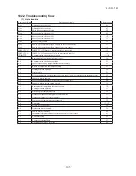
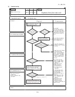
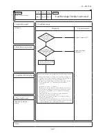
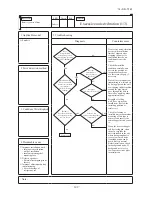
'14 • SR-T-157
LED
U
V
W
LED1
LED3
LED5
LED2
LED4
LED6
LED1
LED3
LED5
LED2
LED4
LED6
LED1
LED3
LED5
LED2
LED4
LED6
LED1
LED3
LED5
LED2
LED4
LED6
LED1
LED3
LED5
LED2
LED4
LED6
LED1
LED3
LED5
LED2
LED4
LED6
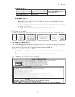
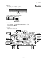
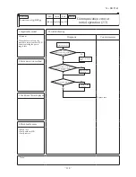
(5)
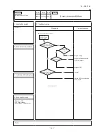
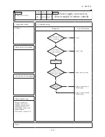
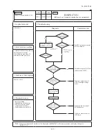
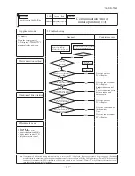
Inverter checker for diagnosis of inverter output
●
Checking method
(a) Setup procedure of checker.
1) Power OFF (Turn off the breaker).
2) Remove the terminal cover of compressor and disconnect the wires (U, V, W) from compressor.
3) Connect the wires U (Red) , V (White) and W (Black) of the checker to the terminal of disconnected wires (U, V, W)
from compressor respectively.
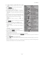
(b) Operation for judgment.
1) Power ON and start check operation on cooling or heating mode.
2) Check ON/OFF status of 6 LED's on the checker.
3) Judge the PCB by ON/OFF status of 6 LED's on the checker.
4) Stop check operation within about 2minutes after starting check operation.
ON/OFF
status of LED
If all of LED are ON/OFF
according to following pattern
If all of LED stay OFF or
some of LED are ON/OFF
Outdoor PCB
Normal
Anomalous
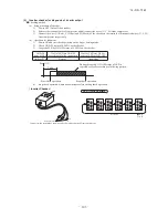
Power ON
3 min.
Start check operation
Stop check operation
During this period, ON/OFF status of LED is
repeated cyclically according to following pattern
Cyclically
●
ON
○
OFF
Red
Black
White
Faston terminal
〈
Inverter Checker
〉
Connect to the terminal of the wires which are disconnected from compressor.
LED ON/OFF pattern
Содержание SRR25ZJ-S
Страница 30: ... 29 14 SR T 157 2 4way ceiling cassette type FDTC Models FDTC25VF 35VF 35 ...
Страница 34: ... 33 14 SR T 157 See page 29 a PJA012D783 ...
Страница 86: ... 85 14 SR T 157 09 SRK DB 087D Service data record form 78 ...
Страница 164: ... 163 14 SR T 157 5 Super link E board SC ADNA E F SL2NA E and SL3N AE BE to control 5 Super link E board SC ADNA E ...
Страница 165: ... 164 14 SR T 157 ...