


-
99
-
'14 • SR-T-157
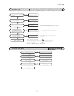
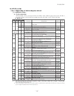
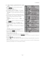
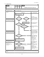
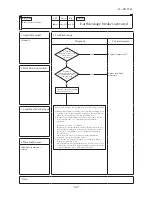
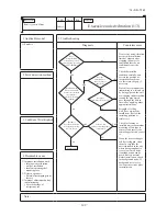
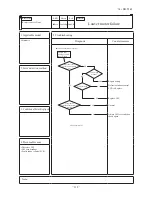
Replace and set up the PCB according to this instruction.
①
Set to an appropriate address and function using switch on PCB.
Select the same setting with the removed PCB.
②
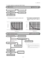
Set to an appropriate capacity using the model selector switch(SW6).
Select the same capacity with the PCB removed from the unit.
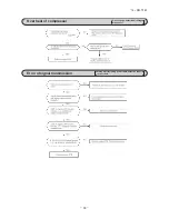
③
Replace the PCB
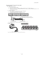
1. Fix the PCB so as not to pitch the cords.
2. Connect connectors to the PCB. Connect a cable connector with the PCB connector of the same color.
3.Do not pass CPU surrounding about wirings.
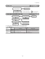
④
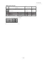
Control PCB
Parts mounting are different by the kind of PCB.
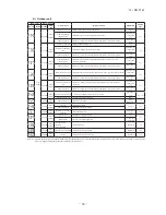
〇:ON -:OFF
Part number
SW2 (Blue)
Address setting
SW7
Function setting
CNT(Blue)
External switch
CNJ(White)
Louver motor
CNN(Yellow)
Thermistor
(Heat exchanger)
CNI(Blue)
Float
SW
CNH(Black)
Thermist
or
(Ret
urn a
ir)
CNW3(Red)
Power PCB
CNB(White)
Remot
e
control
CNG(Blue)
CNZ(White)
HA
CNE(White)
RAM checker
CNW4(Blue)
Power PCB
SW6
Capacity setting
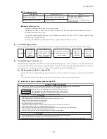
item
switch
Address
SW2
-
〇
Content of control
Plural indoor units control by 1 remote control
Test run
SW7-1
Normal
Operation check/drain motor test run
SW6
ON
1 2 3 4
Example setting fro 25VF
SW6
-1
-2
-3
-4
25VF
〇
〇
-
-
-
35VF
-
-
-
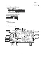
• Control PCB
PSB012D976B
Содержание SRR25ZJ-S
Страница 30: ... 29 14 SR T 157 2 4way ceiling cassette type FDTC Models FDTC25VF 35VF 35 ...
Страница 34: ... 33 14 SR T 157 See page 29 a PJA012D783 ...
Страница 86: ... 85 14 SR T 157 09 SRK DB 087D Service data record form 78 ...
Страница 164: ... 163 14 SR T 157 5 Super link E board SC ADNA E F SL2NA E and SL3N AE BE to control 5 Super link E board SC ADNA E ...
Страница 165: ... 164 14 SR T 157 ...