5
PROCEDURES AND SETTINGS BEFORE OPERATION
5
- 13
5.4 Wiring
5.4.1 Controller network system
5.4.1
Controller network system
The following explains precautions for connecting the optical fiber cables with the CC-Link
IE Controller Network board.
(1) Precautions for connection
(a) Use the dedicated optical fiber cable shown below for the controller network
system.
(b) When connecting an optical fiber cable to the CC-Link IE Controller Network
board, the cable bend radius is restricted.
For details, check the specifications of the cable used.
(c) When laying the optical fiber cables, do not touch the fiber cores of the cable-side
and board-side connectors, and protect them from dirt and dust.
If oil from the hand, dirt or dust is attached to the core, it can increase
transmission loss, causing a problem in data link.
(d) When connecting or disconnecting an optical fiber cable, hold the connector part
of the cable.
(e) Make a full connection between the cable-side and board-side connectors until a
"click" can be heard.
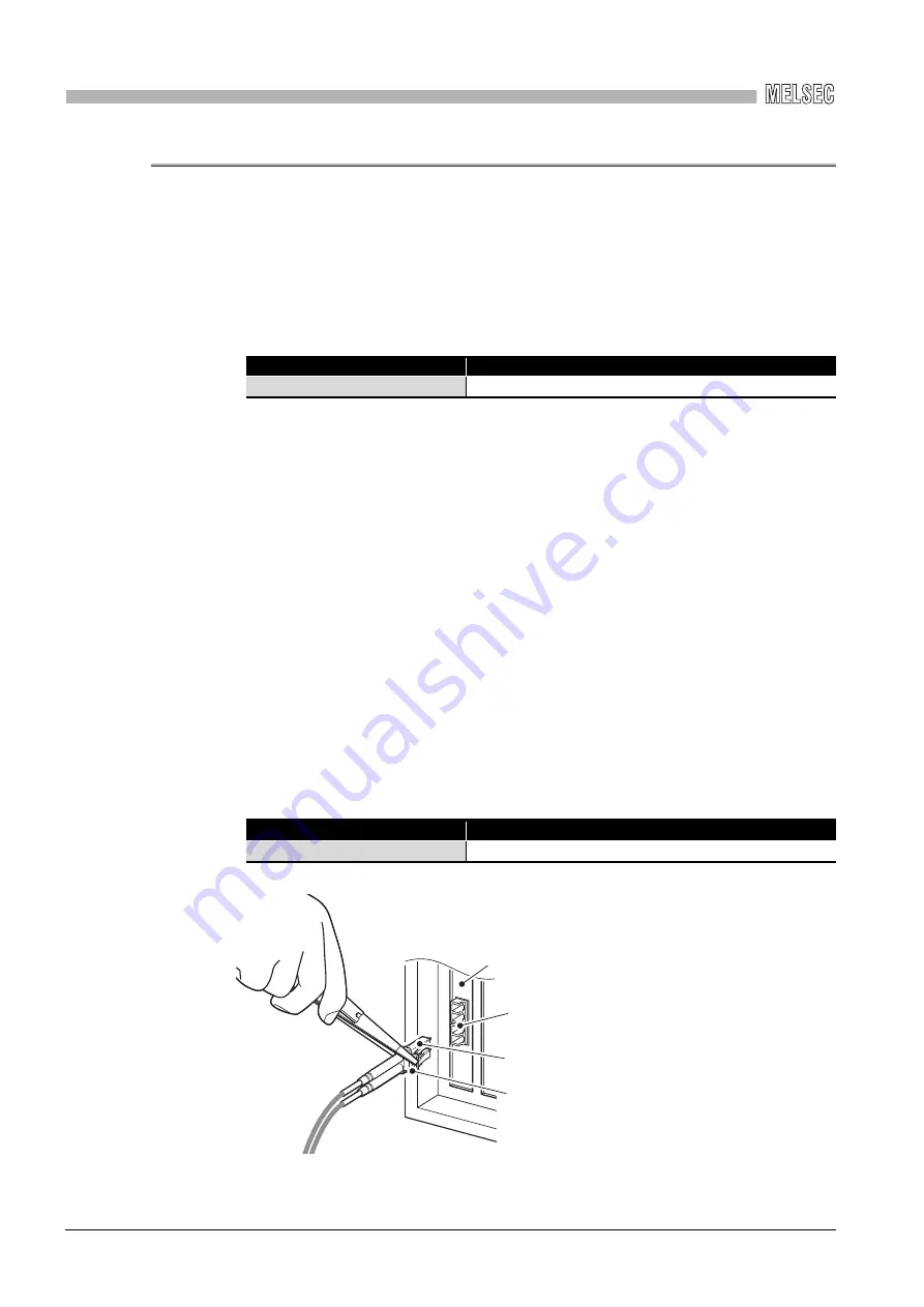
(f) When installing the CC-Link IE Controller Network board to the personal
computer, secure a space of around 10 mm (0.39 in.) to the right and left of the
optical connector. Depending on the adjacent boards and installing slot position,
connecting/disconnecting the optical cable may be difficult. In this case, use the
following dedicated tool.
Type
Model name (maker)
Multi-mode fiber (GI)
QG series (Mitsubishi electric system & service Co., Ltd.)
Model name
Maker
SCT-SLM
Mitsubishi electric system & service Co., Ltd.
Connector hook
Board-side connector
CC-Link IE Controller Network board
Cable-side connector


