


TM
1
7510-A2-GN10-30
January 1999
Model 7510 DSU
Startup Instructions
Document Number 7510-A2-GN10-30
January 1999
Product Documentation on the World Wide Web
We provide complete product documentation online. This lets you search the
documentation for specific topics and print only what you need, reducing the
waste of surplus printing. It also helps us maintain competitive prices for our
products.
Complete documentation for this product is available at www.paradyne.com.
Select
Service & Support
→
Technical Manuals
→
Subrate Digital Access
Devices.
Select the following document:
7510-A2-GB20
Model 7510 DSU User’s Guide
To request a paper copy of a Paradyne document:
Within the U.S.A., call 1-800-PARADYNE (1-800-727-2396)
Outside the U.S.A., call 1-727-530-8623
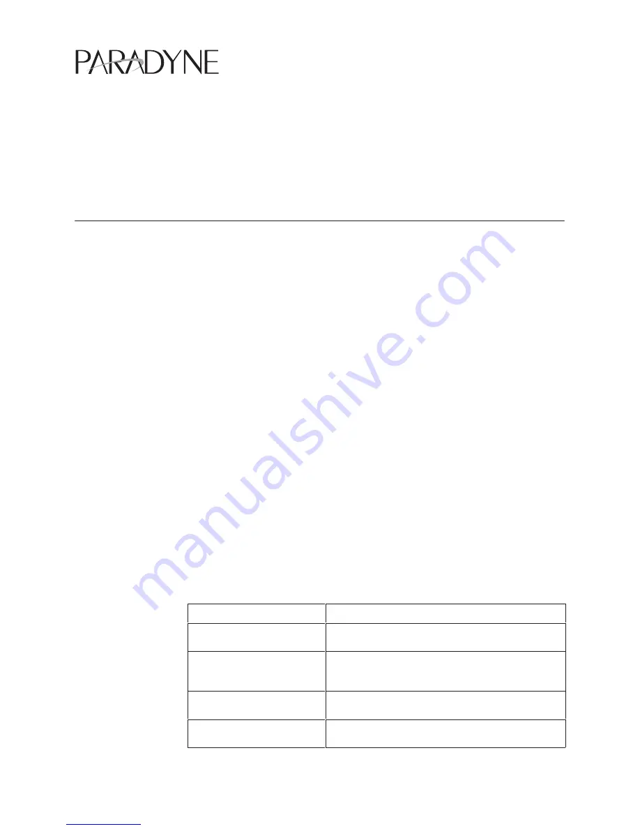
Cables You May Need to Order
The following table describes typical equipment. Identify the connectors required
for your equipment before you contact your sales or service representative to
order cables. For cable details, refer to Appendix C,
Cables and Pin
Assignments, in the User’s Guide.
If connecting . . .
Order a . . .
A VT100-compatible terminal
to the Terminal port
Standard straight-through EIA-232 cable with DB25
plug connectors on both ends.
A PC to the Terminal port
Standard straight-through EIA-232 cable with a DB25
plug connector on one end and a DB9 or DB25 socket
connector, as required, on the other end.
An External Modem to the
Terminal port
Standard crossover EIA-232 cable with DB25 plug
connectors on both ends.
A DTE with a V.35 connector
to the DTE port
V.35 cable with an MS34 plug connector on one end
and an MS34 socket connector on the other end.


