APPENDICES
App
- 9
Appendix 1 Precautions for Accessing Redundant CPU System
Remarks
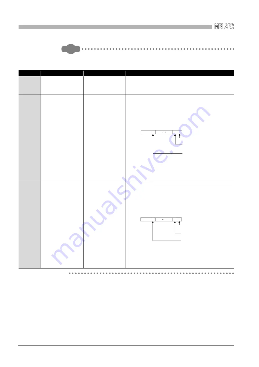
The following table explains details of the special relay and special registers to be
monitored when estimating the occurrence of path switching.
No.
Name
Description
Description details
SM1600
Other system error flag
OFF: No error
ON: Error
• Turns ON when an error occurs by redundant system error
check. (Turns ON when any of bits for SD1600 turns ON.)
• Remains OFF when no errors are present.
SD1590
No. of module for
which system
switching request is
issued from the
network module in own
system
No. of module for
which system
switching request is
issued from the
network module in own
system
• Any of the following bits turns on corresponding to the No.
of the module for which system switching request is issued
from the network module in own system.
• Turned OFF by the system after the error of the relevant
module is resolved by the user.
• For No. of module for which system switching request is
issued from the network module in another system, refer to
SD1690.
SD1690
No. of module for
which system
switching request is
issued from the
network module in
another system
No. of module for
which system
switching request is
issued from the
network module in
another system
• Any of the following bits turns on corresponding to the No.
of the module for which system switching request is issued
from the network module in another system.
• Turned OFF by the system after the error of the relevant
module is resolved by the user.
• For No. of module for which system switching request is
issued from the network module in own system, refer to
SD1590.
b1 b0
b15
b11
to
to
0
0/1
0/1
0
Module No.0: Disabled since a CPU
module uses two slots.
Module to the right of a
CPU module
Rightmost module on 1
2-slot base unit
(Q312B)
Module No.1:
to
Module No.11:
SD1590
Each bit
0: OFF
1: ON
b0
0
0/1
0/1
0
SD1690
b1
b15
b11
to
to
Module No.0: Disabled since a CPU
module uses two slots.
Module to the right of a
CPU module
Rightmost module on
12-slot base unit
(Q312B)
Module No.1:
to
Module No.11:
Each bit
0: OFF
1: ON


