4 - 20
4. OPERATION AND FUNCTIONS
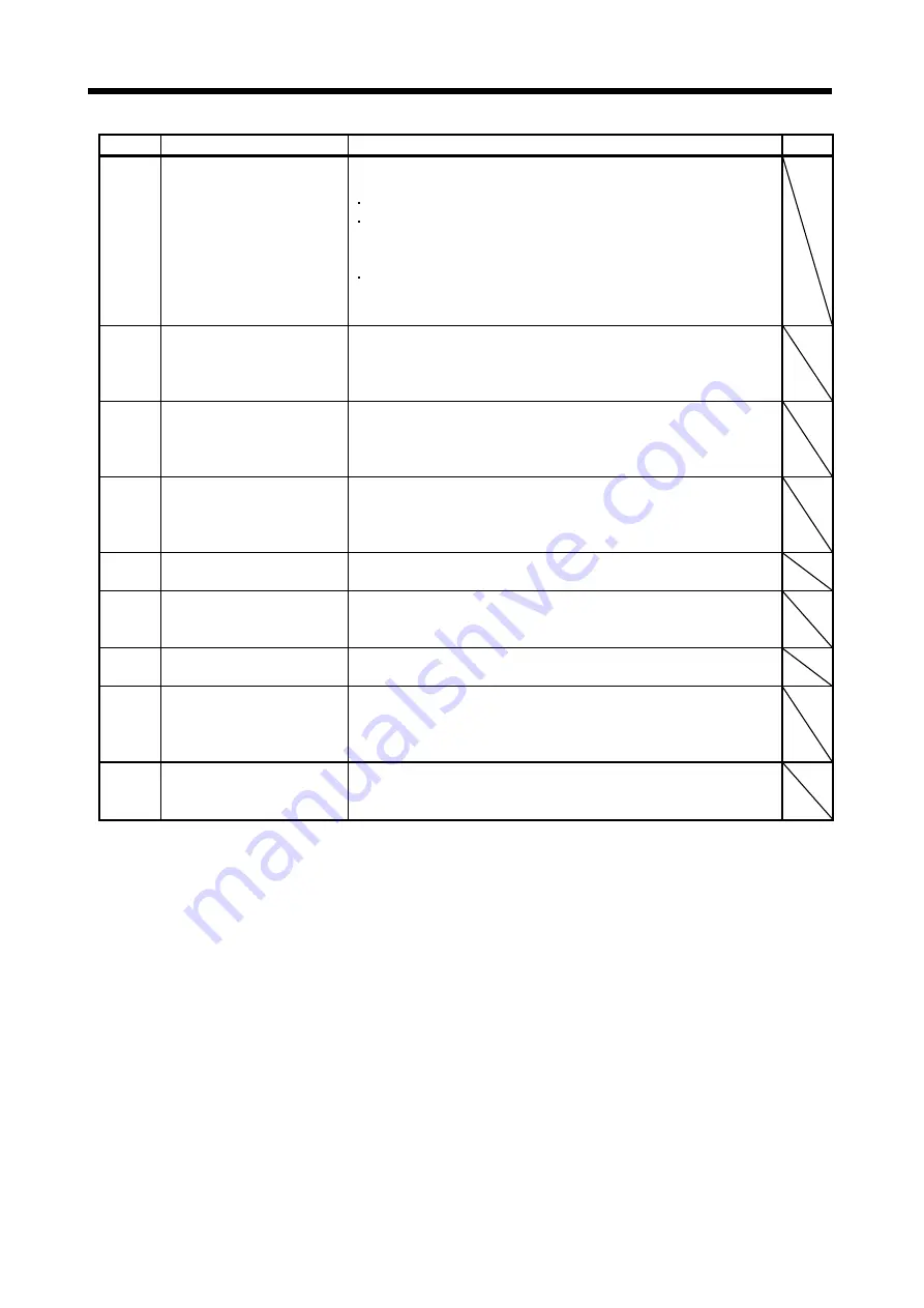
Symbol Name
Explanation
Unit
g)
Encoder information
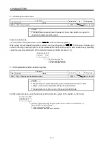
The load side encoder information is displayed.
The display contents differ depending on the load side encoder type.
ID: The ID No. of the load side encoder is displayed.
Data 1: For the incremental type linear encoder, the counter from powering
ON is displayed. For the absolute position type linear encoder, the
absolute position data is displayed.
Data 2: For the incremental type linear encoder, the distance (number of
pulses) from the reference mark (Z-phase) is displayed. For the absolute
position type linear encoder, "00000000" is displayed.
h)
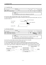
Polarity
A polarity is indicated as " + " or " – " according to the load side encoder
polarity specified in parameter No.PC27. For address increasing direction in
the motor CCW, it is indicated as " + " and for address decreasing direction
in the motor CCW, as " – ".
i)
Z-phase pass status
If the fully closed loop system is "Invalid", the Z-phase pass status of the
motor encoder is displayed. If the fully closed loop system is "Valid" or "Semi
closed loop control/fully closed loop control switching", the Z-phase pass
status of the load side encoder is displayed.
j) Fully
closed
loop
changing
device
Only if the fully closed loop system is "Semi closed loop control/fully closed
loop control switching", the device is displayed.
The state of the semi closed loop control/fully closed loop control switching
bit and the inside state during selection are displayed.
k)
Monitor display
Click the "Monitor start" button to start monitoring.
Click the "Monitor stop" button to stop monitoring.
l)
Parameter read
Click the "Parameter read" button to read all the parameter settings that can
be set and displayed on this window from the servo amplifier and display
them.
m)
Parameter write
Click the "Parameter write" button to write the all parameter settings set and
displayed on this window to the servo amplifier.
n) Parameter
(Feedback
pulse
electronic gear)
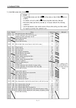
The feedback pulse electronic gears (parameter No.PE04, PE05, PE34,
PE35) are displayed/set for motor encoder pulses in this parameter. (Refer to
section 4.1.5.)
For details of each parameter, refer to section 5.5.2.
o)
Parameter (Dual feedback filter) The band of dual feedback filter (parameter No.PE08) is displayed/set in this
parameter.
For details of parameter, refer to section 5.5.2.
Содержание MR-J3-B-RJ006
Страница 15: ...A 14 MEMO ...
Страница 19: ...4 MEMO ...
Страница 65: ...2 18 2 SIGNALS AND WIRING MEMO ...
Страница 119: ...4 22 4 OPERATION AND FUNCTIONS MEMO ...
Страница 145: ...6 6 6 TROUBLESHOOTING MEMO ...
Страница 155: ...7 10 7 OUTLINE DRAWINGS MEMO ...
Страница 165: ...SH NA 030056 C ...

