WWW.NNC.IR
15 - 63
15. ABSOLUTE POSITION DETECTION SYSTEM
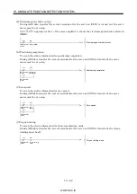
5) Restoring absolute position data
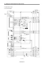
The slot number and buffer address of the A1SD75 home position address reading area are
changed from [DFROP H0001 K7912 D9 K1] to [DFROP H0000 K72 D9 K1] 12).
6) Writing absolute position data to A1SD75
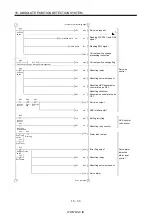
The slot number and buffer address of the X-axis current value changing area are changed from
[DTOP H0001 K41 D3 K1] to [DTOP H0000 K1154 D3 K1] 14). When the current value is changed
in the A1SD75, the current feed value is changed at the start of positioning data No.9003.
Therefore, the starting program for positioning data No.9003 15) is added.
7) X-axis data set type home position return program
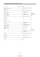
The slot numbers and buffer addresses of the X-axis home position address changing area are
changed from [DTOP H0001 K7912 D9 K1] to [DTOP H0000 K72 D9 K1] and from [DFROP
H0001 K7912 D9 K1] to [DFROP H0000 K72 D9 K1] 17).
The slot number and buffer address of the X-axis current value changing area are changed from
[DTOP H0001 K41 D3 K1] to [DTOP H0000 K1154 D3 K1] 18). When the current value is changed
in the A1SD75, the current feed value is changed at the start of positioning data No.9003.
Therefore, the starting program for positioning data No.9003 19) is added.
8) Y-axis sequence program, Y-axis data set type home position return program.
The slot numbers and buffer addresses are changed as indicated by 20).
9) Writing absolute position data to A1SD75
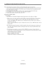
The A1SD75 allows the current position to be changed only when the ready (RD) of the Servo
amplifier is on. Therefore, if the CPU scan is fast, the program for A1SD71 may change the
current position before the ready (RD) switches on. 7) is added because the current position must
be changed after it has been confirmed that the drive unit ready (RD) of the A1SD75 (D75) has
switched on/off.
10) ABS coordinate error detection
As the A1SD75 can handle the negative-polarity coordinate position that the A1SD71 could
not handle, the program for ABS coordinate error detection is deleted 13).
11) Dog type home position return program
Due to the changes in wiring described in (4) (a) 4) in this section, the program for outputting
the clear (CR) (Y35) after completion of a home position return is required 16).
Содержание MR-J2S-*A
Страница 13: ...WWW NNC IR A 12 MEMO ...
Страница 117: ...WWW NNC IR 3 70 3 SIGNALS AND WIRING MEMO ...
Страница 185: ...WWW NNC IR 7 12 7 GENERAL GAIN ADJUSTMENT MEMO ...
Страница 195: ...WWW NNC IR 8 10 8 SPECIAL ADJUSTMENT FUNCTIONS MEMO ...
Страница 197: ...WWW NNC IR 9 2 9 INSPECTION MEMO ...
Страница 221: ...WWW NNC IR 11 10 11 OUTLINE DIMENSION DRAWINGS MEMO ...
Страница 293: ...WWW NNC IR 13 64 13 OPTIONS AND AUXILIARY EQUIPMENT MEMO ...
Страница 321: ...WWW NNC IR 14 28 14 COMMUNICATION FUNCTIONS MEMO ...
Страница 389: ...WWW NNC IR 15 68 15 ABSOLUTE POSITION DETECTION SYSTEM MEMO ...

