WWW.NNC.IR
15 - 6
15. ABSOLUTE POSITION DETECTION SYSTEM
15.6 Startup procedure
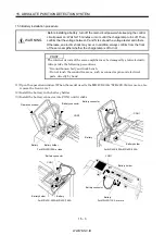
(1) Battery installation.
Refer to section 15.3 installation of absolute position backup battery.
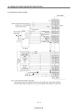
(2) Parameter setting
Set "1 "in parameter No. 1 of the servo amplifier and switch power off, then on.
(3) Resetting of absolute position erase (AL.25)
After connecting the encoder cable, the absolute position erase (AL.25) occurs at first power-on. Leave
the alarm as it is for a few minutes, then switch power off, then on to reset the alarm.
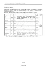
(4) Confirmation of absolute position data transfer
When the servo-on (SON) is turned on, the absolute position data is transferred to the programmable
controller. When the ABS data is transferred properly.
(a) The ready output (RD) turns on.
(b) The programmable controller/ABS data ready contact (M3 for A1SD71, M99 for 1PG) turns on.
(c) The MR Configurator (servo configuration software) ABS data display window (refer to section
15.9) and programmable controller side ABS data registers (D3, D4 for A1SD71, D106, D107 for
1PG) show the same value (at the home position address of 0).
If any warning such as ABS time-out warning (AL.E5) or programmable controller side transfer
error occurs, refer to section 15.10 or chapter 10 and take corrective action.
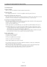
(5) Home position setting
The home position must be set if.
(a) System setup is performed.
(b) The servo amplifier has been changed.
(c) The servo motor has been changed; or
(d) The absolute position erase (AL.25) occurred.
In the absolute position system, the absolute position coordinates are made up by making home
position setting at the time of system setup.
The servo motor may operate unexpectedly if positioning operation is performed without home
position setting. Always make home position setting before starting operation.
For the home position setting method and types, refer to section 15.7.3.
Содержание MR-J2S-*A
Страница 13: ...WWW NNC IR A 12 MEMO ...
Страница 117: ...WWW NNC IR 3 70 3 SIGNALS AND WIRING MEMO ...
Страница 185: ...WWW NNC IR 7 12 7 GENERAL GAIN ADJUSTMENT MEMO ...
Страница 195: ...WWW NNC IR 8 10 8 SPECIAL ADJUSTMENT FUNCTIONS MEMO ...
Страница 197: ...WWW NNC IR 9 2 9 INSPECTION MEMO ...
Страница 221: ...WWW NNC IR 11 10 11 OUTLINE DIMENSION DRAWINGS MEMO ...
Страница 293: ...WWW NNC IR 13 64 13 OPTIONS AND AUXILIARY EQUIPMENT MEMO ...
Страница 321: ...WWW NNC IR 14 28 14 COMMUNICATION FUNCTIONS MEMO ...
Страница 389: ...WWW NNC IR 15 68 15 ABSOLUTE POSITION DETECTION SYSTEM MEMO ...

