background image


13 -  2 

13. CHARACTERISTICS 


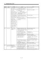
13.2 Power supply equipment capacity and generated loss 

(1) Amount of heat generated by the servo amplifier 

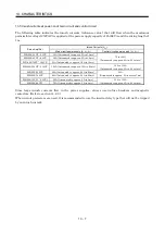
Table 12.1 indicates servo amplifier's power supply capacities and losses generated under rated load. 
For thermal design of an enclosure, use the values in Table 13.1 in consideration for the worst 
operating conditions. The actual amount of generated heat will be intermediate between values at 
rated torque and servo-off according to the duty used during operation. When the servo motor is run at 
less than the maximum speed, the power supply capacity will be smaller than the value in the table, 
but the servo amplifier's generated heat will not change. 


Table 13.1 Power supply capacity and generated heat per servo amplifier at rated output 

(Note 2) 

Servo amplifier-generated heat[W] 

Area required for heat dissipation 

Servo amplifier 

Servo motor 

(Note 1) 

Power supply 
capacity[kVA] 

At rated torque 

With servo off 

[m

2

] [ft

2

HC-KFS053 13 0.3 

25 

15 

0.5 

5.4 

HC-MFS053 13 0.3 

25 

15 

0.5 

5.4 

MR-J2S-10CP(1) 

HC-UFS13 0.3  25  15  0.5  5.4 
HC-KFS23 0.5  25  15  0.5  5.4 
HC-MFS23 0.5  25  15  0.5  5.4 

MR-J2S-20CP(1) 

HC-UFS23 0.5  25  15  0.5  5.4 
HC-KFS43 0.9  35  15  0.7  7.5 
HC-MFS43 0.9  35  15  0.7  7.5 

MR-J2S-40CP(1) 

HC-UFS43 0.9  35  15  0.7  7.5 
HC-SFS52 1.0 40  15  0.8 8.6 
HC-SFS53 1.0 40  15  0.8 8.6 

MR-J2S-60CP 

HC-LFS52 1.0 40  15  0.8 8.6 
HC-KFS73 1.3  50  15  1.0 10.8 
HC-MFS73 1.3  50  15  1.0 10.8 

MR-J2S-70CP 

HC-UFS72 73 1.3 

50 

15 

1.0 

10.8 

HC-SFS81 1.5 50  15  1.0 10.8 
HC-SFS102 103 1.7 

50 

15 

1.0 

10.8 

MR-J2S-100CP 

HC-LFS102 1.7  50  15  1.0  10.8 
HC-SFS121 2.1  90  20  1.8  19.4 
HC-SFS201 3.5  90  20  1.8  19.4 
HC-SFS152 153 2.5 

90 

20 

1.8 

19.4 

HC-SFS202 203 3.5 

90 

20 

1.8 

19.4 

HC-RFS103 1.8  50  15  1.0  10.8 
HC-RFS153 2.5  90  20  1.8  19.4 
HC-UFS152 2.5  90  20  1.8  19.4 

MR-J2S-200CP 

HC-LFS152 2.5  90  20  1.8  19.4 
HC-SFS301 4.8  120  20  2.7  29.1 
HC-SFS352 353 5.5 

130 

20 

2.7 

29.1 

HC-RFS203 3.5  90  20  1.8  19.4 
HC-UFS202 3.5  90  20  1.8  19.4 

MR-J2S-350CP  

HC-LFS202 3.5  90  20  1.8  19.4 
HC-SFS502 7.5  195  25  3.9  42.0 
HC-RFS353 5.5  135  25  2.7  29.1 
HC-RFS503 7.5  195  25  3.9  42.0 
HC-UFS352 5.5  195  25  3.9  42.0 
HC-UFS502 7.5  195  25  3.9  42.0 
HC-LFS302 4.5  120  25  2.4  25.8 

MR-J2S-500CP


HA-LFS502 7.5  195  25  3.9  42.0 
HC-SFS702 10.0  300  25  6.0  64.6 

MR-J2S-700CP 

HA-LFS702 10.6  300  25  6.0  64.6 

Note 1. Note that the power supply capacity will vary according to the power supply impedance. This value assumes that the power 

factor improving reactor is not used. 

2. Heat generated during regeneration is not included in the servo amplifier-generated heat. To calculate heat generated by the 

regenerative option, Refer to section 14.1.1. 


Содержание MR-J2S-10CP

Страница 1: ...ions subject to change without notice This Instruction Manual uses recycled paper MODEL MR J2S CP SERVO AMPLIFIER INSTRUCTION MANUAL Built In Positioning Function MR J2S CP Servo Amplifier Instruction Manual MODEL MODEL CODE J2 Super Series G G HEAD OFFICE TOKYO BLDG MARUNOUCHI TOKYO 100 8310 ...

Страница 2: ...ous conditions resulting in death or severe injury CAUTION Indicates that incorrect handling may cause hazardous conditions resulting in medium or slight injury to personnel or may cause physical damage Note that the CAUTION level may lead to a serious consequence according to conditions Please follow the instructions of both levels because they are important to personnel safety What must not be d...

Страница 3: ...k 2 To prevent fire note the following CAUTION Install the servo amplifier servo motor and regenerative resistor on incombustible material Installing them directly or close to combustibles will lead to a fire Always connect a magnetic contactor MC between the main circuit power supply and L1 L2 and L3 of the servo amplifier and configure the wiring to be able to shut down the power supply on the s...

Страница 4: ...e servo amplifier and servo motor Do not drop or strike servo amplifier or servo motor Isolate from all impact loads When you keep or use it please fulfill the following environmental conditions Conditions Environment Servo amplifier Servo motor 0 to 55 non freezing 0 to 40 non freezing In operation 32 to 131 non freezing 32 to 104 non freezing 20 to 65 non freezing 15 to 70 non freezing Ambient t...

Страница 5: ...orber or radio noise filter FR BIF option between the servo motor and servo amplifier Connect the output terminals U V W correctly Otherwise the servo motor will operate improperly Connect the servo motor power terminal U V W to the servo motor power input terminal U V W directly Do not let a magnetic contactor etc intervene U Servo motor M V W U V W U M V W U V W Servo amplifier Servo motor Servo...

Страница 6: ...designed to hold the motor shaft and should not be used for ordinary braking For such reasons as service life and mechanical structure e g where a ballscrew and the servo motor are coupled via a timing belt the electromagnetic brake may not hold the motor shaft To ensure safety install a stopper on the machine side 5 Corrective actions CAUTION When it is assumed that a hazardous condition may take...

Страница 7: ... using the products for special purposes such as nuclear power electric power aerospace medicine passenger movement vehicles or underwater relays contact Mitsubishi These products have been manufactured under strict quality control However when installing the product where major accidents or losses could occur if the product fails install appropriate backup or failsafe functions in the system EEP ...

Страница 8: ... EMC Installation Guidelines IB NA 67310 2 Low voltage directive The low voltage directive applies also to servo units alone Hence they are designed to comply with the low voltage directive This servo is certified by TUV third party assessment organization to comply with the low voltage directive 3 Machine directive Not being machines the servo amplifiers need not comply with this directive 2 PREC...

Страница 9: ...imping terminals provided with insulating tubes to prevent contact with adjacent terminals Crimping terminal Insulating tube Cable b Use the servo motor side power connector which complies with the EN Standard The EN Standard compliant power connector sets are available from us as options Refer to section 14 1 4 7 Auxiliary equipment and options a The circuit breaker and magnetic contactor used sh...

Страница 10: ...er Discharge time min MR J2S 10CP 1 20CP 1 1 MR J2S 40CP 1 60CP 2 MR J2S 70CP to 350CP 3 MR J2S 500CP 700CP 5 5 Options and auxiliary equipment Use UL C UL standard compliant products 6 Attachment of a servo motor For the flange size of the machine side where the servo motor is installed refer to CONFORMANCE WITH UL C UL STANDARD in the Servo Motor Instruction Manual 7 About wiring protection For ...

Страница 11: ...A 10 MEMO ...

Страница 12: ...dard connection example 3 2 3 2 Internal connection diagram of servo amplifier 3 3 3 3 I O signals 3 4 3 3 1 Connectors and signal arrangements 3 4 3 3 2 Signal devices explanations 3 5 3 4 Detailed description of signals devices 3 13 3 4 1 Forward rotation start Reverse rotation start Temporary stop restart 3 13 3 4 2 Movement finish Rough match In position 3 14 3 4 3 Override 3 16 3 4 4 Torque l...

Страница 13: ...on return 4 26 4 4 2 Dog type home position return 4 28 4 4 3 Count type home position return 4 30 4 4 4 Data setting type home position return 4 31 4 4 5 Stopper type home position return 4 32 4 4 6 Home position ignorance servo on position defined as home position 4 34 4 4 7 Dog type rear end reference home position return 4 35 4 4 8 Count type front end reference home position return 4 36 4 4 9...

Страница 14: ... Display flowchart 7 1 7 2 Status display 7 2 7 2 1 Display transition 7 2 7 2 2 Display examples 7 3 7 2 3 Status display list 7 4 7 3 Diagnosis mode 7 5 7 3 1 Display transition 7 5 7 3 2 Diagnosis mode list 7 6 7 4 Alarm mode 7 8 7 4 1 Display transition 7 8 7 4 2 Alarm mode list 7 9 7 5 Point table mode 7 11 7 5 1 Point table transition 7 11 7 5 2 Point table mode setting screen sequence 7 12 ...

Страница 15: ...ELSERVO J2 and MELSERVO J2 Super 8 11 8 5 1 Response level setting 8 11 8 5 2 Auto tuning selection 8 11 9 SPECIAL ADJUSTMENT FUNCTIONS 9 1 to 9 10 9 1 Function block diagram 9 1 9 2 Machine resonance suppression filter 9 1 9 3 Adaptive vibration suppression control 9 3 9 4 Low pass filter 9 4 9 5 Gain changing function 9 5 9 5 1 Applications 9 5 9 5 2 Function block diagram 9 5 9 5 3 Parameters 9...

Страница 16: ...isplay MR DP60 14 30 14 1 8 Manual pulse generator MR HDP01 14 32 14 1 9 Battery MR BAT A6BAT 14 33 14 2 Auxiliary equipment 14 34 14 2 1 Recommended wires 14 34 14 2 2 Circuit breakers fuses magnetic contactors 14 36 14 2 3 Power factor improving reactors 14 36 14 2 4 Relays 14 37 14 2 5 Surge absorbers 14 37 14 2 6 Noise reduction techniques 14 38 14 2 7 Leakage current breaker 14 45 14 2 8 EMC ...

Страница 17: ...devices ON OFF test operation 15 26 15 12 8 Test operation mode 15 27 15 12 9 Output signal pin ON OFF output signal DO forced output 15 30 15 12 10 Alarm history 15 31 15 12 11 Current alarm 15 32 15 12 12 Point table 15 33 15 12 13 Servo amplifier group designation 15 39 15 12 14 Software version 15 40 APPENDIX App 1 to App 4 App 1 Status indication block diagram App 1 App 2 Junction terminal bl...

Страница 18: ... introduced here for your reference Note that the contents of the Servo Motor Instruction Manual are not included in the Servo Amplifier Instruction Manual 1 INTRODUCTION 2 INSTALLATION 3 CONNECTORS USED FOR SERVO MOTOR WIRING 4 INSPECTION 5 SPECIFICATIONS 6 CHARACTERISTICS 7 OUTLINE DIMENSION DRAWINGS 8 CALCULATION METHODS FOR DESIGNING ...

Страница 19: ...8 MEMO ...

Страница 20: ...an be increased up to 31 points by using the MR Configurator servo configuration software You can choose a configuration suitable for your purpose e g simple positioning system using external I O signals DI O operation using DI O and RS 422 serial communication or multi drop operation using RS 422 serial communication All servo motors are equipped with an absolute position encoder as standard An a...

Страница 21: ...alog 2 channels To other servo amplifier RS 422 RS 232C Controller Analog monitor 2 channels 1 31 8 7 6 5 4 3 2 1000 2000 4000 500 1000 2000 1000 1000 2000 2000 1000 1000 2000 2000 2000 2000 1000 80 100 70 60 80 80 80 100 80 80 100 70 60 80 80 100 80 1000 500 0 0 0 0 0 0 0 0 0 0 0 0 0 1 1 No Model adaptive control Current control Position control Speed control Position command creation Auxiliary D...

Страница 22: ... D A CN3 CON1 MR BAT Optional battery for absolute position detection system D I O control Servo on Start Failure etc Analog 2 channels To other servo amplifier RS 422 RS 232C Controller Analog monitor 2 channels 1 31 8 7 6 5 4 3 2 1000 2000 4000 500 1000 2000 1000 1000 2000 2000 1000 1000 2000 2000 2000 2000 1000 80 100 70 60 80 80 80 100 80 80 100 70 60 80 80 100 80 1000 500 0 0 0 0 0 0 0 0 0 0 ...

Страница 23: ...1 mm 0 01 mm 0 1 mm 1 mm Servo motor speed 0 to max speed r min Acceleration time constant 0 to 20000 ms Deceleration time constant 0 to 20000 ms Dwell 0 to 20000 ms Auxiliary function 0 to 3 Refer to section 4 2 1 Operation using external input signals a Description The following configuration example assumes that external input signals are used to control all signals devices The I O signals are ...

Страница 24: ...ward rotation start ST1 or reverse rotation start ST2 through the external I O Use this system when position data speed setting or the host personal computer or the like is used to change the parameter values for example b Configuration 1 One servo amplifier is connected with the personal computer by RS 232C MR Configurator Servo configuration Software Servo amplifier External I O signals Power su...

Страница 25: ...e communication system MR Configurator Servo configuration Software Servo amplifier axis 1 External I O signals Power supply Servo motor RS 422 Personal computer CN1A CN1B CN2 CN3 Servo amplifier axis 2 External I O signals Servo motor CN1A CN1B CN2 CN3 RS 232C RS 232C RS 422 converter to be prepared by the customer To the next axis RS 422 Power supply ...

Страница 26: ...d through communication Also you can set each point table choose the point table and change or set parameter values for example Up to 32 axes may be controlled b Configuration 1 One servo amplifier is connected with the personal computer by RS 232C MR Configurator Servo configuration Software Servo amplifier External I O signals Power supply Servo motor RS 232C Personal computer CN1A CN1B CN2 CN3 ...

Страница 27: ...e communication system MR Configurator Servo configuration Software Servo amplifier axis 1 External I O signals Power supply Servo motor RS 422 Personal computer CN1A CN1B CN2 CN3 Servo amplifier axis 2 External I O signals Servo motor CN1A CN1B CN2 CN3 RS 232C RS 232C RS 422 converter to be prepared by the customer To the next axis RS 422 Power supply ...

Страница 28: ...B 19 Reverse rotation start ST2 CN1B 9 Electromagnetic brake interlock MBR Automatic manual selection MD0 CN1B 7 Position range output POT Point table No selection 1 DI0 CN1B 5 Warning output WNG Point table No selection 2 DI1 CN1B 14 Battery warning output BWNG Point table No selection 3 DI2 Limiting torque TLC Point table No selection 4 DI3 Temporary stop PUS Point table No selection 5 DI4 In po...

Страница 29: ...through RS 422 232C communication Acceleration deceleration time is also set through RS 422 232C communication S pattern acceleration deceleration time constant is set in parameter No 14 Command system Position data input System Signed absolute value command system incremental value command system signed absolute value command incremental value command specifying system Point table Point table num...

Страница 30: ... proximity dog by the first Z phase pulse Home position address may be set Home position shift value may be set Home position return direction may be set Automatic at dog home position return return automatic stroke return function Operation mode Automatic positioning to home position High speed automatic return to a defined home position Other functions Absolute position detection backlash functi...

Страница 31: ... characteristics automatically to suppress mechanical vibration Section 9 3 Low pass filter Suppresses high frequency resonance which occurs as servo system response is increased Section 9 4 Machine analyzer function Analyzes the frequency characteristic of the mechanical system by simply connecting a MR Configurator servo configuration software installed personal computer and servo amplifier Mach...

Страница 32: ...speed can be changed between 0 to 200 Section 3 4 3 Status display The servo status is displayed Section 7 2 Test operation mode Jog operation positioning operation motor less operation DO forced output 1 step feed Section 6 7 Limit switch The servo motor travel region can be limited using the forward rotation stroke end LSP reverse rotation stroke end LSN Section 5 2 5 Software limit The travel r...

Страница 33: ...y to the models with electromagnetic brakes and the models with reduction gears Servo motors HC SFS HC UFS Servo amplifier HC KFS HC MFS 1000r min 2000r min 3000r min HC RFS 2000r min 3000r min MR J2S 10CP 1 053 13 053 13 13 MR J2S 20CP 1 23 23 23 MR J2S 40CP 1 43 43 43 MR J2S 60CP 52 53 MR J2S 70CP 73 73 72 73 MR J2S 100CP 81 102 103 MR J2S 200CP 121 201 152 202 153 203 103 153 152 MR J2S 350CP 3...

Страница 34: ... monitor data Name plate Charge lamp Lit to indicate that the main circuit is charged While this lamp is lit do not reconnect the cables Encoder connector CN2 Used to connect the servo motor encoder Main circuit terminal block TE1 Used to connect the input power supply and servo motor Protective earth PE terminal Ground terminal Section4 5 Operation section Used to perform status display diagnosti...

Страница 35: ...ation connector CN3 Used to connect a command device RS 422 RS 232C and output analog monitor data Name plate Charge lamp Lit to indicate that the main circuit is charged While this lamp is lit do not reconnect the cables Encoder connector CN2 Used to connect the servo motor encoder Main circuit terminal block TE1 Used to connect the input power supply and servo motor Protective earth PE terminal ...

Страница 36: ...ed to change the mode I O signal connector CN1A Used to connect digital I O signals Section3 3 Section3 3 I O signal connector CN1B Used to connect digital I O signals Chapter6 Chapter15 Section14 1 4 Communication connector CN3 Used to connect a command device RS 422 RS 232C and output analog monitor data Encoder connector CN2 Used to connect the servo motor encoder Section3 3 Section14 1 4 Charg...

Страница 37: ...ed to change the mode I O signal connector CN1A Used to connect digital I O signals Section3 3 I O signal connector CN1B Used to connect digital I O signals Section3 3 Communication connector CN3 Used to connect a command device RS 422 RS 232C and output analog monitor data Chapter6 Chapter15 Section14 1 4 Charge lamp Lit to indicate that the main circuit is charged While this lamp is lit do not r...

Страница 38: ...ver socket 2 places 2 1 Front cover 2 1 Removal of the front cover Reinstallation of the front cover 1 Insert the front cover hooks into the front cover sockets of the servo amplifier 2 Press the front cover against the servo amplifier until the removing knob clicks 1 Hold down the removing knob 2 Pull the front cover toward you 2 For MR J2S 500CP Front cover socket 2 places Removal of the front c...

Страница 39: ...nt cover 1 Insert the two front cover hooks at the bottom into the sockets of the servo amplifier 2 Press the front cover against the servo amplifier until the removing knob clicks 1 Push the removing knob A or B and put you finger into the front hole of the front cover 2 Pull the front cover toward you A 2 B 2 1 Front cover hook 2 places ...

Страница 40: ...1 Encoder cable Note 1 Power supply lead L3 Power factor improving reactor FR BAL Options and auxiliary equipment Circuit breaker Magnetic contactor MR Configurator Servo configuration software Regenerative option Reference Section 14 2 2 Section 14 2 2 Chapter 6 Section 14 1 1 Options and auxiliary equipment Reference Cables Manual pulse generator External digital display Section 14 2 1 Section 1...

Страница 41: ...r factor improving reactor FR BAL Options and auxiliary equipment Circuit breaker Magnetic contactor Reference Section 14 2 2 Section 14 2 2 Options and auxiliary equipment Reference Cables Manual pulse generator External digital display Section 14 2 1 Section 14 1 8 Section 14 1 7 Power factor improving reactor Section 14 2 3 Junction terminal block Manual pulse generator External digital display...

Страница 42: ...rnal digital display Section 14 2 1 Section 14 1 8 Section 14 1 7 Power factor improving reactor FR BAL Note Power supply Circuit breaker NFB or fuse Magnetic contactor MC To CN2 To CN3 To CN1B To CN1A L1 L2 L3 L21 L11 Servo amplifier Regenerative option P C U V W Personal computer MR Configurator Servo configuration software MRZJW3 SETUP151E Power factor improving reactor Section 14 2 3 Junction ...

Страница 43: ...splay Personal computer MR Configurator Servo configuration software MRZJW3 SETUP151E Options and auxiliary equipment Circuit breaker Magnetic contactor Reference Section 14 2 2 Section 14 2 2 Options and auxiliary equipment Reference Cables Manual pulse generator External digital display Section 14 2 1 Section 14 1 8 Section 14 1 7 Power factor improving reactor Section 14 2 3 Power factor improv...

Страница 44: ... 1 7 Power factor improving reactor Section 14 2 3 Command device Junction terminal block Manual pulse generator External digital display Personal computer MR Configurator Servo configuration software MRZJW3 SETUP151E To CN1A To CN1B To CN3 To CN2 Note 1 U V W L1 L2 L3 Power factor improving reactor FR BAL Magnetic contactor MC L11 L21 Circuit breaker NFB or fuse Note 2 Power supply Servo amplifie...

Страница 45: ...1 26 1 FUNCTIONS AND CONFIGURATION MEMO ...

Страница 46: ...not block the intake exhaust ports of the servo amplifier Otherwise a fault may occur Do not subject the servo amplifier to drop impact or shock loads as they are precision equipment Do not install or operate a faulty servo amplifier When the product has been stored for an extended period of time consult Mitsubishi When treating the servo amplifier be careful about the edged parts such as the corn...

Страница 47: ...t must be installed in the specified direction Otherwise a fault may occur Leave specified clearances between the servo amplifier and control box inside walls or other equipment 1 Installation of one servo amplifier Control box Control box 10mm 0 4 in or more 10mm 0 4 in or more 40mm 1 6 in or more 40mm 1 6 in or more Wiring clearance 70mm 2 8 in Servo amplifier Up Down ...

Страница 48: ...of heat generation so that the servo amplifier is not affected Install the servo amplifier on a perpendicular wall in the correct vertical direction 2 3 Keep out foreign materials 1 When installing the unit in a control box prevent drill chips and wire fragments from entering the servo amplifier 2 Prevent oil water metallic dust etc from entering the servo amplifier through openings in the control...

Страница 49: ... and brake wiring cables Use the optional encoder cable within the flexing life range Use the power supply and brake wiring cables within the flexing life of the cables 3 Avoid any probability that the cable sheath might be cut by sharp chips rubbed by a machine corner or stamped by workers or vehicles 4 The flexing lives of the cables are shown below In actuality provide a little allowance for th...

Страница 50: ...st fault etc Ensure that polarity is correct Otherwise a burst damage etc may occur The surge absorbing diode installed to the DC relay designed for control output should be fitted in the specified direction Otherwise the signal is not output due to a fault disabling the forced stop EMG and other protective circuits Control output signal COM 24VDC Servo amplifier RA RA Control output signal COM 24...

Страница 51: ...ctive earth PE terminal of the servo amplifier to the protective earth PE of the control box 2 Connect the diode in the correct direction If it is connected reversely the servo amplifier will be faulty and will not output signals disabling the forced stop and other protective circuits 3 CN1A CN1B CN2 and CN3 have the same shape Wrong connection of the connectors will lead to a fault 4 The sum of c...

Страница 52: ...B 3 13 9 8 5 7 8 9 14 15 16 17 10 20 10 20 OPC PG PP NG NP SD 11 13 3 12 2 Casing CN1A CN1B VC TLA P15R LG SD 2 12 11 1 Casing CN1A P15R 4 24VDC Approx 4 7k Approx 4 7k Approx 4 7k Approx 4 7k Approx 4 7k Approx 4 7k Approx 4 7k Approx 4 7k Approx 100 Approx 1 2k Approx 1 2k 15VDC ZP CPO MEND ALM RD 18 4 6 18 19 CN1A CN1B CN1A 16 7 17 5 14 1 15 6 LG MO1 4 CN3 MO2 LA LAR LB LZ LZR OP LBR 14 2 12 9 ...

Страница 53: ...P TXD MO2 P5 LG LG RDN SDN 1 2 3 5 4 6 7 9 8 10 11 12 13 14 15 16 17 18 19 20 1 2 3 5 4 6 7 9 8 10 11 12 13 14 15 16 17 18 19 20 1 2 3 5 4 6 7 9 8 10 11 12 13 14 15 16 17 18 19 20 MD LG MDR P5 LG MRR P5 LG P5 BAT MR LG Servo amplifier CN2 CN3 CN1A CN1B The connector frames are connected with the PE earth terminal inside the servo amplifier LG NP P15R DOG SG COM PP OPC ZP SG LG SG SG COM SON LSN MD...

Страница 54: ...e using the MR Configurator servo configuration software CN1B 4 Rough match CPO CN1B 6 Movement finish MEND CN1B 18 Trouble ALM CN1B 19 Ready RD Output only pins CN1A 18 DO 1 Home position return completion ZP b Input devices Device name Devices symbol Connector pin No Functions Applications Forced stop EMG When EMG SG are opened the servo amplifier is placed in the forced stop status the servo sw...

Страница 55: ... rotation denotes the direction in which the address is incremented 3 In absolute value command incremental value command specifying system When ST1 SG are shorted in the automatic operation mode positioning is executed once on the basis of the position data set to the point table In home position return mode home position return starts as soon as ST1 SG are shorted In jog operation mode the servo...

Страница 56: ... on short Override selection OVR Short OVR SG to make override VC valid External torque limit selection TL Short TL SG to make external analog torque limit valid For more information refer to section 3 4 4 Internal torque limit selection TL2 Open TL2 SG to make the torque limit value set in parameter No 28 TL1 valid or short them to make the value set in parameter No 29 TL2 valid For more informat...

Страница 57: ...generator multiplication 1 TP0 Used to select the multiplication factor of the manual pulse generator When it is not selected the parameter No 1 setting is made valid Note Input signal TP1 TP0 Manual pulse generator multiplication factor 0 0 Parameter No 1 setting 0 1 1 time 1 0 10 times 1 1 100 times Manual pulse generator multiplication 2 TP1 Note 0 TP1 TP0 SG open 1 TP1 TP0 SG shorted Gain swit...

Страница 58: ...inate system 000 in parameter No 1 has been changed 11 Software limit is valid 12 Home position return completion If the status is not any of 1 to 12 and the home position setting has already been completed at least once home position return completion ZP is placed in the same output status as ready RD Electromagnetic brake interlock MBR In the servo off or alarm status MBR SG are disconnected Whe...

Страница 59: ...1 1 1 16 1 0 0 0 0 17 1 0 0 0 1 18 1 0 0 1 0 19 1 0 0 1 1 20 1 0 1 0 0 21 1 0 1 0 1 22 1 0 1 1 0 23 1 0 1 1 1 24 1 1 0 0 0 25 1 1 0 0 1 26 1 1 0 1 0 27 1 1 0 1 1 28 1 1 1 0 0 29 1 1 1 0 1 30 1 1 1 1 0 31 1 1 1 1 1 Note 0 DI SG open 1 DI SG shorted Point table No output 5 PT4 In any of the following states PT0 to PT4 SG are opened Power on Servo off During home position return Home position return ...

Страница 60: ...ns I O division Encoder Z phase pulse open collector OP CN1A 14 Outputs the zero point signal of the encoder One pulse is output per servo motor revolution OP and LG are connected when the zero point position is reached Negative logic The minimum pulse width is about 400 s For home position return using this pulse set the creep speed to 100r min or less DO 2 Encoder A phase pulse differential line...

Страница 61: ...B 3 Used to output 24V 10 to across VDD SG When using this power supply for digital interface connect it with COM Permissible current 80mA Digital I F power supply input COM CN1A 9 CN1B 13 Used to input 24VDC 200mA or more for input interface Connect the positive terminal of the 24VDC external power supply 24VDC 10 Open collector power input OPC CN1A 11 When you use a manual pulse generator supply...

Страница 62: ... start signal changes from OFF to ON The delay time of the servo amplifier s internal processing is max 3ms The delay time of other signals is max 10ms Servo motor speed Forward rotation start ST1 or reverse rotation start ST2 3ms or less 3ms or less 5ms or more Temporary stop Restart STP 10ms or less 3 When a programmable controller is used the ON time of the start stop signal should be 5ms or lo...

Страница 63: ...ommand and servo motor speed 3ms or less In position range Servo motor speed Position command OFF ON OFF ON Movement finish MEND When parameter No 6 is small Forward rotation start ST1 or reverse rotation start ST2 Position command and servo motor speed Movement finish MEND 3ms or less In position range Servo motor speed Position command OFF ON OFF ON When parameter No 6 is large 2 Rough match The...

Страница 64: ...servo on status ON OFF ON OFF Forward rotation start ST1 or reverse rotation start ST2 Servo motor speed In position INP 3ms or less In position range When positioning operation is performed once Forward rotation start ST1 or reverse rotation start ST2 ON OFF ON OFF Servo motor speed In position INP In position range 3ms or less Reverse rotation Forward rotation When servo motor reverses rotation ...

Страница 65: ...ph shows the relationship between the input voltage and the ratio of actual speed to preset speed Override selection OVR OVR SG VC LG Servo amplifier Override VC Override VC application voltage Ratio of actual speed to preset speed 10 10 200 0 V 0 100 SD 10 to 10V 2 Override selection OVR Used to make the override VC valid or invalid Servo amplifier Override selection OVR Override Override VC 10 t...

Страница 66: ...og input signal This function limits torque on the assumption that the maximum torque of the servo motor is 100 1 Internal torque limits 1 2 Use parameter No 28 and 29 to set the internal torque limit values The following graph shows the torque relative to the setting Max torque 0 0 100 Torque limit value Torque 2 Analog torque limit TLA By applying a voltage 0 to 10V to the analog torque limit TL...

Страница 67: ...eter No 28 Parameter No 29 1 1 TLA Parameter No 29 Parameter No 29 TLA Parameter No 29 TLA Note 0 TL TL2 SG off open 1 TL TL2 SG on short 4 External torque limit offset parameter No 26 Using parameter No 26 the offset voltage can be set relative to the input voltage of the analog torque limit TLA The setting is between 999 to 999mV 5 Selection of rotation direction for torque limit execution param...

Страница 68: ... off the main circuit power as soon as an alarm occurs 1 Overcurrent overload 1 or overload 2 If operation is repeated by switching control circuit power off then on to reset the overcurrent AL 32 overload 1 AL 50 or overload 2 AL 51 alarm after its occurrence without removing its cause the servo amplifier and servo motor may become faulty due to temperature rise Securely remove the cause of the a...

Страница 69: ...1A CN1B RA DO 1 Manual pulse generator MR HDP01 A B 0V 5V PP NP SG 5V SG Isolated 15VDC 10 30mA P15R TLA VC etc LG SD Analog input 10V max current Differential line driver output 35mA or less Single phase 100 to 200VAC Analog monitor LG E L1 L2 Servo motor encoder CN2 MR MRR SD MO1 MO2 CN3 LG SDP SDN RDP RDN LG SD Servo motor M Ground LG SD LA etc LAR etc LG OP TXD TXD RXD RXD ...

Страница 70: ...nect VDD COM Servo amplifier Note This also applies to the use of the external power supply 2 Digital output interface DO 1 A lamp relay or photocoupler can be driven Provide a diode D for an inductive load or an inrush current suppressing resister R for a lamp load Permissible current 40mA or less inrush current 100mA or less A maximum of 2 6V voltage drop occurs in the servo amplifier a Inductiv...

Страница 71: ...f 2 6V interferes with the relay operation apply high voltage up to 26 4V from external source 3 Encoder pulse output DO 2 a Open collector system Interface Servo amplifier OP 5 to 24VDC Photocoupler SD Max output current 35mA LG Servo amplifier OP SD LG b Differential line driver system 1 Interface Max output current 35mA LA LB LZ LAR LBR LZR LG SD LA LB LZ LAR LBR LZR SD Servo amplifier Servo am...

Страница 72: ...termined by the setting of the parameter No 27 and 58 4 Analog input Input impedance 10k to 12k Upper limit setting 2k 15VDC P15R VC etc LG SD 2k Servo amplifier Approx 10k 5 Analog output Output voltage 10V Max 1mA Max output current Resolution 10bits MO1 MO2 LG SD A Servo amplifier Reading in one or both directions 1mA meter 10k ...

Страница 73: ...o amplifier Note This also applies to the use of the external power supply Since source output is not provided make the following circuit For use of internal power supply For use of external power supply COM ALM etc SG Load Servo amplifier VDD 24VDC If the polarity of diode is not correct the servo amplifier will become faulty COM ALM etc SG Load Servo amplifier VDD 24VDC Do not connect VDD COM No...

Страница 74: ...lifier malfunctions Use the trouble signal to switch power off Otherwise a regenerative transistor fault or the like may overheat the regenerative resistor causing a fire 3 7 1 Connection example Wire the power supply and main circuit as shown below so that the servo on SON turns off as soon as alarm occurrence is detected and power is shut off A circuit breaker NFB must be used with the input cab...

Страница 75: ...r 1 phase 230VAC power supply RA OFF ON MC MC SK NFB MC L1 L2 L3 L11 L21 EMG SON SG VDD COM ALM RA Power supply 1 phase 100 to 120VAC or 1 phase 230VAC Forced stop Servo on Note Servo amplifier Trouble Forced stop Note Not provided for 1 phase 100 to 120VAC ...

Страница 76: ...to 230VAC 50 60Hz L11 L21 1 phase 100 to 120VAC 50 60Hz L11 L21 L11 L21 Control circuit power supply P C D Regenerative option 1 MR J2S 350CP or less When using servo amplifier built in regenerative resistor connect between P D terminals Wired by default When using regenerative option disconnect between P D terminals and connect regenerative option to P terminal and C terminal 2 MR J2S 500CP or 70...

Страница 77: ...t 1 to 2s and the ready RD will switch on in further about 20ms making the servo amplifier ready to operate Refer to paragraph 2 of this section 4 When the reset RES is switched on the base circuit is shut off and the servo motor shaft coasts 2 Timing chart 20ms 20ms 20ms 10ms 10ms 10ms 10ms 10ms 60ms 60ms SON accepted 1 to 2s ON OFF ON OFF ON OFF ON OFF ON OFF Power supply Base circuit Servo on S...

Страница 78: ...the earth cable of the servo motor to the protective earth PE terminal of the servo amplifier and connect the ground cable of the servo amplifier to the earth via the protective earth of the control box Do not connect them directly to the protective earth of the control panel Servo amplifier Servo motor PE terminal Control box 2 Do not share the 24VDC interface power supply between the interface a...

Страница 79: ... To be shut off when servo on SON switches off or by Trouble ALM 24VDC EMG CN2 U V W U V W B1 B2 Servo amplifier Note 1 Encoder Encoder cable Motor Servo motor Note 1 To prevent an electric shock always connect the protective earth PE terminal of the servo amplifier to the protective earth PE of the control box 2 This circuit applies to the servo motor with electromagnetic brake HC SFS81 B HC SFS5...

Страница 80: ...oder cable 0 3m 0 98ft Power supply lead 4 AWG19 0 3m 0 98ft With connector 1 172169 9 Tyco Electronics 1 2 3 4 1 2 5 4 3 6 1 2 3 5 6 Power supply connector 5557 04R 210 Pin Signal Earth U V W Power supply connector 5557 06R 210 Pin Signal Earth U V W MR 1 2 3 MRR BAT MD 4 5 6 MDR P5 7 8 9 LG SHD Encoder connector signal arrangement B1 B2 Note Note Note For the motor with electromagnetic brake sup...

Страница 81: ... U V W Note B2 Earth Key Note B1 CE05 2A22 23PD B Power supply connector signal arrangement Pin A B C D E F G U V W CE05 2A24 10PD B Signal Earth Note B2 Note B1 Note For the motor with electromagnetic brake supply electromagnetic brake power 24VDC There is no polarity View c View c D C B A A B C D E F G H A B C D E F G Pin A B C D U V W Signal Earth Key Key CE05 2A32 17PD B Note For the motor wit...

Страница 82: ...ed with electromagnetic brake is used 1 In the device setting of the MR Configurator servo configuration software make the electromagnetic brake interlock MBR available 2 Do not share the 24VDC interface power supply between the interface and electromagnetic brake Always use the power supply designed exclusively for the electromagnetic brake 3 The brake will operate when the power 24VDC switches o...

Страница 83: ...tation start ST2 Electromagnetic brake Release delay time and external relay Note 2 Note 3 ON OFF Note 1 ON Electromagnetic brake is not activated OFF Electromagnetic brake is activated 2 Electromagnetic brake is released after delaying for the release delay time of electromagnetic brake and operation time of external circuit relay For the release delay time of electromagnetic brake refer to the S...

Страница 84: ...ivated OFF Electromagnetic brake is activated d Both main and control circuit power supplies off 10ms 10ms Electromagnetic brake operation delay time Note 1 15 to 60ms Electromagnetic brake Dynamic brake Electromagnetic brake Dynamic brake ON Forward rotation Electromagnetic brake interlock MBR Servo motor speed Base circuit Trouble ALM ON OFF ON OFF Note 2 0r min No Yes OFF Main circuit Control c...

Страница 85: ...rotation Electromagnetic brake interlock MBR Servo motor speed Base circuit Trouble ALM ON OFF ON OFF Note 3 0r min No Yes OFF Main circuit power supply ON OFF Note 1 15 or more Note 1 Changes with the operating status 2 When the main circuit power supply is off in a motor stop status the main circuit off warning AL E9 occurs and the trouble ALM does not turn off 3 ON Electromagnetic brake is not ...

Страница 86: ...f the transistor To prevent such a fault refer to the following diagram and always ground To conform to the EMC Directive refer to the EMC Installation Guidelines IB NA 67310 Control box Servo amplifier L1 L2 L3 L11 L21 CN1A CN1B Line filter NFB MC Protective earth PE CN2 U V W Outer box Servo motor Ensure to connect it to PE terminal of the servo amplifier Do not connect it directly to the protec...

Страница 87: ...re to avoid a short caused by the loose wires of the core and the adjacent pole Do not solder the core as it may cause a contact fault Alternatively a bar terminal may be used to put the wires together 2 When the wires are put together Using a bar terminal Cable Size Bar Terminal Type mm2 AWG For 1 cable For 2 cables Crimping Tool Manufacturer 1 25 1 5 16 AI1 5 10BK AI TWIN 1 5 10BK 2 2 5 14 AI2 5...

Страница 88: ...er or the like Twisted wire When removing the short circuit bar from across P D press the buttons of P and D alternately pulling the short circuit bar For the installation insert the bar straight to the end b When the wires are put together using a bar terminal Insert a bar terminal with the odd shaped side of the pressured terminal on the button side Bar terminal for one wire or solid wire Bar te...

Страница 89: ...ult Alternatively a bar terminal may be used to put the wires together Cable size Bar terminal type mm 2 AWG For 1 cable For 2 cables Crimping tool Manufacturer 1 25 1 5 16 AI1 5 10BK AI TWIN 1 5 10BK 2 2 5 14 AI2 5 10BU CRIMPFOX ZA3 or CRIMPFOX UD 6 Phoenix Contact 2 Connection Insert the core of the cable into the opening and tighten the screw with a flat blade screwdriver so that the cable does...

Страница 90: ...wdriver is recommended to manage the screw tightening torque The following table indicates the recommended products of the torque screwdriver for tightening torque management and the flat blade bit for torque screwdriver When managing torque with a Phillips bit please consult us Product Model Manufacturer Representative Torque screwdriver N6L TDK Nakamura Seisakusho Bit for torque screwdriver B 30...

Страница 91: ...e like securely connect the shielded external conductor of the cable to the ground plate as shown in this section and fix it to the connector shell External conductor Sheath External conductor Pull back the external conductor to cover the sheath Sheath Core Strip the sheath Screw Screw Ground plate Cable ...

Страница 92: ...generation converter 1 For the MR J2S 350CP or less the lead has been removed from across D P of the control circuit terminal block and twisted cables are used for its wiring 2 For the MR J2S 500CP or more the lead has been removed from across P C of the servo amplifier built in regenerative resistor and twisted cables are used for its wiring f When stroke end limit switches are used the signals a...

Страница 93: ...erly alone For startup reference a single machine structure will be described Refer to this section and start up the machine safely 1 Machine conditions Point table No 1 Servo motor HC MFS131072pulse rev Servo motor speed Ballscrew PB 10mm 0 39inch Reduction ratio 1 n 1 2 Servo amplifier Regenerative option MR RB032 Ta Tb 0r min V Position data P 200mm 787 40inch Speed V 2500r min Acceleration tim...

Страница 94: ...Description No 0 Command system regenerative option selection No 1 Feeding function selection No 2 Function selection 1 20 Absolute value command system MR RB032 regenerative option is used 10 When forward rotation start ST1 is valid address is incremented in CCW direction Since command resolution is 10 times feed length multiplication factor of 10 times is selected Absolute position detection sys...

Страница 95: ...nd LSN ON CW rotation side limit switch is turned on Servo on SON ON Servo is switched on g Automatic operation Set the input signals as listed below and switch on the forward rotation start ST1 to execute automatic operation in accordance with point table No 1 Device name Symbol ON OFF Description Automatic manual selection MD0 ON Automatic operation mode is selected Servo on SON ON Servo is swit...

Страница 96: ...ress to be reached Setting range 999999 to 999999 10STM m STM feed length multiplication parameter No 1 Position data setting range 10 m 999999 999999 STM b Incremental value command system As position data set the moving distance from the current address to the target address Setting range 0 to 999999 10STM m STM feed length multiplication parameter No 1 Current address Target address Position da...

Страница 97: ...on time constant Deceleration time constant Set the deceleration time constant Dwell Set the waiting time when performing automatic continuous operation Auxiliary function Set when performing automatic continuous operation b Selection of point table Using the input signal or communication function select the point table No with a command from the command device controller such as a personal comput...

Страница 98: ... 1 1 7 0 1 0 0 0 8 0 1 0 0 1 9 0 1 0 1 0 10 0 1 0 1 1 11 0 1 1 0 0 12 0 1 1 0 1 13 0 1 1 1 0 14 0 1 1 1 1 15 1 0 0 0 0 16 1 0 0 0 1 17 1 0 0 1 0 18 1 0 0 1 1 19 1 0 1 0 0 20 1 0 1 0 1 21 1 0 1 1 0 22 1 0 1 1 1 23 1 1 0 0 0 24 1 1 0 0 1 25 1 1 0 1 0 26 1 1 0 1 1 27 1 1 1 0 0 28 1 1 1 0 1 29 1 1 1 1 0 30 1 1 1 1 1 31 Note 1 Make signals valid in I O Devices on the MR Configurator servo configuration...

Страница 99: ...ervo motor is reached Deceleration time constant 0 to 20000 ms Set the deceleration time constant Set the time until the servo motor running at rated speed comes to a stop Dwell 0 to 20000 ms Set the dwell Set 0 in the auxiliary function to make the dwell invalid Set 1 in the auxiliary function and 0 in the dwell to perform continuous operation When the dwell is set the position command of the sel...

Страница 100: ...ition data input range mm 0 999 999 to 999 999 1 9999 99 to 9999 99 2 99999 9 to 99999 9 3 999999 to 999999 3 Operation Choose the point table using DI0 to DI4 and short ST1 SG to perform positioning to the position data under the conditions of the preset speed acceleration time constant and deceleration time constant At this time reverse rotation start ST2 is invalid Item Setting method Descripti...

Страница 101: ... time until the rated speed of the servo motor is reached Deceleration time constant 0 to 20000 ms Set the deceleration time constant Set the time until the servo motor running at rated speed comes to a stop Dwell 0 to 20000 ms Set the dwell Set 0 in the auxiliary function to make the dwell invalid Set 1 in the auxiliary function and 0 in the dwell to perform continuous operation When the dwell is...

Страница 102: ...999 1 0 to 9999 99 2 0 to 99999 9 3 0 to 999999 3 Operation Choose the point table using DI0 to DI4 and short ST1 SG to make a motion in the forward rotation direction over the distance of the position data under the conditions of the preset speed acceleration time constant and deceleration time constant Short ST2 SG to make a motion in the reverse rotation direction in accordance with the point t...

Страница 103: ...ntaneous permissible speed of the servo motor Acceleration time constant 0 to 20000 ms Set the acceleration time constant Set the time until the rated speed of the servo motor is reached Deceleration time constant 0 to 20000 ms Set the deceleration time constant Set the time until the servo motor running at rated speed comes to a stop Dwell 0 to 20000 ms Set the dwell Set 0 or 2 in the auxiliary f...

Страница 104: ...tion data CCW CW c Feed length multiplication selection parameter No 1 Set the unit multiplication factor STM of position data Parameter No 1 setting Position data input range mm 0 0 to 999 999 1 0 to 9999 99 2 0 to 99999 9 3 0 to 999999 3 Operation Choose the point table using DI0 to DI4 and short ST1 SG to perform positioning to the position data under the conditions of the preset speed accelera...

Страница 105: ...put PT0 to PT4 Ready RD Trouble ALM Point table No 1 Note 2 3ms or more 5ms or more 3ms or less Point table No 2 3ms or more Note 1 Reverse rotation start ST2 is invalid in the absolute value command system and absolute value command incremental value command specifying system 2 External input signal detection delays by the input filter setting time of parameter No 2 Also make up a sequence that w...

Страница 106: ...ed speed operation Speed during positioning operation can be changed by setting the auxiliary function of the point table Use the number of point tables equal to the number of speeds to be set By setting 1 to the auxiliary function operation is performed at the speed set in the next point table during positioning The position data valid at this time is the data selected at start and the accelerati...

Страница 107: ...min Acceleration time constant ms Deceleration time constant ms Dwell ms Note 1 Auxiliary function 1 5 00 3000 100 150 0 1 2 10 00 2000 Invalid Invalid 0 1 3 15 00 1000 Invalid Invalid 0 0 Note 2 Note 1 Always set 0 2 Always set 0 to the auxiliary function of the last point table among the consecutive point tables Acceleration time constant of point table No 1 100 Deceleration time constant of poi...

Страница 108: ... speed r min Acceleration time constant ms Deceleration time constant ms Dwell ms Note 1 Auxiliary function 1 10 00 3000 100 150 0 1 2 5 00 2000 Invalid Invalid 0 0 Note 2 Note 1 Always set 0 2 Always set 0 to the auxiliary function of the last point table among the consecutive point tables ON OFF 0 0 5 00 10 00 1 1 Deceleration time constant of point table No 1 150 Acceleration time constant of p...

Страница 109: ...on 1 5 00 3000 100 150 0 1 2 6 00 2000 Invalid Invalid 0 1 3 3 00 1000 Invalid Invalid 0 0 Note 2 Note 1 Always set 0 2 Always set 0 to the auxiliary function of the last point table among the consecutive point tables ON OFF 0 0 5 00 11 00 14 00 1 5 00 6 00 3 00 1 Servo motor speed Position address Selected point table No Forward rotation start ST1 Acceleration time constant of point table No 1 10...

Страница 110: ...on data 10STM m Servo motor speed r min Acceleration time constant ms Deceleration time constant ms Dwell ms Note 1 Auxiliary function 1 5 00 3000 100 150 0 1 2 3 00 2000 Invalid Invalid 0 3 3 10 00 1000 Invalid Invalid 0 1 4 6 00 500 Invalid Invalid 0 0 Note 2 Note 1 Always set 0 2 Always set 0 or 2 to the auxiliary function of the last point table among the consecutive point tables 0 When point ...

Страница 111: ... 3000 100 150 0 1 2 7 00 2000 Invalid Invalid 0 1 3 8 00 1000 Invalid Invalid 0 0 Note 2 Note 1 Always set 0 2 Always set 0 or 2 to the auxiliary function of the last point table among the consecutive point tables 0 When point table is used in absolute value command system 1 When point table is used in incremental value command system ON OFF 0 0 5 00 12 00 1 8 00 7 00 1 Servo motor speed Reverse r...

Страница 112: ...oing and jog operation a When the servo motor is rotating ON OFF ON OFF ON OFF 0 OFF OFF ON ON OFF ON No n Servo motor speed Point table Forward rotation start ST1 or reverse rotation start ST2 Temporary stop Restart STP Temporary stop PUS Rough match CPO In position INP Movement finish MEND Acceleration time constant of point table No n Deceleration time constant of point table No n Remaining dis...

Страница 113: ...t the speed of the servo motor Acceleration deceleration time constant Point table No 1 Use the acceleration deceleration time constants in point table No 1 2 Servo motor rotation direction Servo motor rotation direction Parameter No 1 setting Forward rotation start ST1 ON Reverse rotation start ST2 ON 0 CCW rotation CW rotation 1 CW rotation CCW rotation ST1 ON CCW CW ST2 ON ST2 ON CCW CW ST1 ON ...

Страница 114: ...c manual selection MD0 Rough match CPO Servo motor speed Forward rotation start ST1 Reverse rotation start ST2 Forward rotation jog Reverse rotation jog ON OFF ON OFF ON OFF ON OFF ON OFF ON OFF Forward rotation Reverse rotation ON OFF ON OFF 0r min 80ms Movement finish MEND ...

Страница 115: ...ion refer to 3 of this section Servo motor rotation direction Parameter No 1 Refer to 2 of this section 2 Servo motor rotation direction Servo motor rotation direction Parameter No 1 setting Manual pulse generator forward rotation Manual pulse generator reverse rotation 0 CCW rotation CW rotation 1 CW rotation CCW rotation Forward rotation CCW CW 3 Manual pulse generator multiplication a Using the...

Страница 116: ...enerator multiplication 2 across TP1 Note Pulse generator multiplication 1 across TP0 Multiplication ratio of servo motor rotation to manual pulse generator rotation Moving distance 0 0 Parameter No 1 setting valid 0 1 1 time 1 m 1 0 10 times 10 m 1 1 100 times 100 m Note 0 Open across TP1 TP0 SG 1 Shorted across TP1 TP0 SG 4 Operation Turn the manual pulse generator to rotate the servo motor For ...

Страница 117: ...r Count type home position return With deceleration started at the front end of a proximity dog the position where the first Z phase signal is given after advancement over the preset moving distance after the proximity dog or a motion has been made over the home position shift distance starting from the Z phase signal is defined as a home position Home position return method using a proximity dog ...

Страница 118: ...8 1 Choose the home position return method 2 Choose the starting direction of home position return Set 0 to start home position return in the direction in which the address is incremented from the current position or 1 to start home position return in the direction in which the address is decremented 3 Choose the polarity at which the proximity dog is detected Set 0 to detect the dog when the prox...

Страница 119: ... direction Dog input polarity Parameter No 8 Refer to section 4 4 1 2 and choose dog input polarity Home position return speed Parameter No 9 Set speed until detection of dog Creep speed Parameter No 10 Set speed after detection of dog Home position shift distance Parameter No 11 Set when shifting the home position starting at the first Z phase signal after passage of proximity dog rear end Home p...

Страница 120: ... Home position shift distance Parameter No 11 Home position address Parameter No 42 3ms or less The parameter No 42 home position return position data setting value is the positioning address after the home position return is completed 4 Adjustment In dog type home position return adjust to ensure that the Z phase signal is generated during dog detection Locate the rear end of the proximity dog DO...

Страница 121: ...on return speed Parameter No 9 Set speed until detection of dog Creep speed Parameter No 10 Set speed after detection of dog Home position shift distance Parameter No 11 Set when shifting the home position starting at the first Z phase signal given after passage of the proximity dog front end and movement over the moving distance Moving distance after proximity dog Parameter No 43 Set the moving d...

Страница 122: ...I1 SG OFF Data setting type home position return Parameter No 8 2 Data setting type home position return is selected Home position return position data Parameter No 42 Use to set the current position on completion of home position return 2 Timing chart Movement finish MEND Rough match CPO Home position return completion ZP Servo motor speed Forward rotation start ST1 ON OFF ON OFF ON OFF ON OFF 3m...

Страница 123: ...r No 8 3 Stopper type home position return is selected Home position return direction Parameter No 8 Refer to section 4 4 1 2 and choose the home position return direction Home position return speed Parameter No 9 Set the speed till contact with the stopper Stopper time Parameter No 44 Time from when the part makes contact with the stopper to when home position return data is obtained to output ho...

Страница 124: ...ome position address Parameter No 42 Stopper 3ms or less 5ms or more Stopper time Parameter No 44 Note The torque limit that is enabled at this point is as follows Note I O devices TL1 TL Limit value status Torque limit to be enabled 0 0 Parameter No 45 TLA Parameter No 45 Parameter No 45 0 1 TLA Parameter No 45 TLA Parameter No 29 Parameter No 45 Parameter No 45 1 0 Parameter No 29 Parameter No 4...

Страница 125: ... ignorance is selected Home position return position data Parameter No 42 Use to set the current position on completion of home position return 2 Timing chart Movement finish MEND Rough match CPO Home position return completion ZP Servo motor speed ON OFF ON OFF ON OFF Home position address Parameter No 42 ON OFF Automatic manual selection MD0 Ready RD ON OFF ON OFF Servo on SON The parameter No 4...

Страница 126: ...4 4 1 2 and select the home position return direction Dog input polarity Parameter No 8 Refer to section 4 4 1 2 and select the dog input polarity Home position return speed Parameter No 9 Set the speed till the dog is detected Creep speed Parameter No 10 Set the speed after the dog is detected Home position shift distance Parameter No 11 Set when the home position is moved from where the axis has...

Страница 127: ...direction Parameter No 8 Refer to section 4 4 1 2 and select the home position return direction Dog input polarity Parameter No 8 Refer to section 4 4 1 2 and select the dog input polarity Home position return speed Parameter No 9 Set the speed till the dog is detected Creep speed Parameter No 10 Set the speed after the dog is detected Home position shift distance Parameter No 11 Set when the home...

Страница 128: ...Set the speed till the dog is detected Creep speed Parameter No 10 Set the speed after the dog is detected Home position shift distance Parameter No 11 Set when the home position is moved from the Z phase signal position Home position return acceleration deceleration time constants Point table No 1 Use the acceleration deceleration time constant of point table No 1 Home position return position da...

Страница 129: ...proximity dog then executes home position return at this position 2 When the current position is beyond the proximity dog At a start a motion is made in the home position return direction and an automatic return is made on detection of the stroke end LSP or LSN The motion stops past the front end of the proximity dog and home position return is resumed at that position If the proximity dog cannot ...

Страница 130: ... Parameter used Description Automatic manual selection MD0 Short MD0 SG ON Point table No selection 1 DI0 Open DI0 SG OFF Manual home position return mode selection Point table No selection 2 DI1 Open DI1 SG OFF Home position return speed Parameter No 9 Speed is set up Home position return acceleration time constant Point table No 1 Use the acceleration time constant of point table No 1 Set up the...

Страница 131: ...ing conditions 1 Stroke less coordinate system e g rotary shaft infinite positioning 2 Operation performed in incremental value command type positioning system 2 Specifications Item Description System Electronic battery backup system Battery 1 piece of lithium battery primary battery nominal 3 6V Type MR BAT or A6BAT Maximum revolution range Home position 32767 rev Note 1 Maximum speed at power fa...

Страница 132: ... cumulative revolution counter value retaining time if the cable is unplugged or broken LSO 1XO MR BAT Servo amplifier Point table No selection DI0 to DI3 etc I O circuit Position data speed data current position read Home position return data EEP ROM memory Backup at power off Battery Current position LS Speed detection 1X Detection of position within one revolution Servo motor Within one revolut...

Страница 133: ...eration window CON1 Battery holder CON1 Battery connector Battery Battery holder For MR J2S 100CP or less Battery connector CON1 Battery holder Battery For MR J2S 500CP MR J2S 700CP For MR J2S 200CP MR J2S 350CP 6 Parameter setting Set parameter No 2 Function selection 1 as indicated below to make the absolute position detection system valid Parameter No 2 Selection of absolute position detection ...

Страница 134: ...tioning operation in accordance with point tables By selecting the point table No and switching on the forward rotation start ST1 or reverse rotation start ST2 using the communication function positioning operation in accordance with point tables can be started 1 Selection of point tables Using the device forced output from the controller command 9 2 data No 6 0 choose point tables from among No 1...

Страница 135: ...6 Point table No 1 selection 9 2 6 0 7 Forward rotation start ST1 ON 9 2 6 0 8 Forward rotation start ST1 OFF 9 2 6 0 4 6 3 Multidrop system The RS 422 communication function can be used to operate several servo amplifiers on the same bus In this case set the station numbers to the servo amplifiers to determine the destination servo amplifier of the currently transmitted data Use parameter No 15 t...

Страница 136: ...E MITSUBISHI CHARGE MITSUBISHI CHARGE MITSUBISHI CHARGE MITSUBISHI CHARGE MITSUBISHI Group d Group c To CN3 Group a Controller Axis 1 Station 0 Axis 2 Station 1 Axis 3 Station 2 Axis 4 Station 3 Axis 5 Station 4 Group b To CN3 To CN3 To CN3 To CN3 For cable connection diagram refer to section 15 1 1 Axis 6 Station 5 To CN3 Axis 7 Station 6 To CN3 Axis 8 Station 7 To CN3 Axis 9 Station 8 To CN3 Axi...

Страница 137: ...oup a 9 2 6 0 2 Forward rotation start ST1 ON 9 2 6 0 3 Forward rotation start ST1 OFF 9 2 6 0 4 Selection of point table No 1 of group b 9 2 6 0 5 Forward rotation start ST1 ON 9 2 6 0 6 Forward rotation start ST1 OFF 9 2 6 0 7 Selection of point table No 1 of group c 9 2 6 0 8 Forward rotation start ST1 ON 9 2 6 0 9 Forward rotation start ST1 OFF 9 2 6 0 10 Selection of point table No 1 of group...

Страница 138: ...frequencies of use In the factory setting condition the customer can change the basic parameter values but cannot change the expansion parameter 1 2 values and special parameter values When fine adjustment e g gain adjustment is required change the parameter No 19 setting to make the expansion parameters write enabled The following table lists the parameters whose values are made valid for referen...

Страница 139: ...to tuning 0105 4 CMX Electronic gear numerator 1 5 CDV Electronic gear denominator 1 6 INP In position range 100 pulse 7 PG1 Position control gain 1 35 rad s 8 ZTY Home position return type 0010 9 ZRF Home position return speed 500 r min 10 CRF Creep speed 10 r min 11 ZST Home position shift distance 0 m 12 CRP Rough match output range 0 10STM m 13 JOG Jog speed 100 r min 14 STC S pattern accelera...

Страница 140: ...c brake sequence output 100 ms 34 GD2 Ratio of load inertia moment to Servo motor inertia moment 70 0 1 times 35 PG2 Position control gain 2 35 rad s 36 VG1 Speed control gain 1 177 rad s 37 VG2 Speed control gain 2 817 rad s 38 VIC Speed integral compensation 48 ms 39 VDC Speed differential compensation 980 40 0 41 For manufacturer setting 0 42 ZPS Home position return position data 0 10STM m 43 ...

Страница 141: ...on suppression control 0000 64 GD2B Ratio of load inertia moment to Servo motor inertia moment 2 70 0 1 times 65 PG2B Position control gain 2 changing ratio 100 66 VG2B Speed control gain 2 changing ratio 100 67 VICB Speed integral compensation changing ratio 100 68 CDP Gain changing selection 0000 69 CDS Gain changing condition 10 Note 70 CDT Gain changing time constant 1 ms 71 100 72 10000 73 10...

Страница 142: ...ction selection Used to set the feed length multiplication factor and manual pulse generator multiplication factor ST1 coordinate system selection Refer to section 4 2 2 to 4 2 4 0 Address is incremented in CCW direction 1 Address is incremented in CW direction Feed length multiplication factor STM Refer to section 4 2 2 to 4 2 4 0 1 time 1 10 times 2 100 times 3 1000 times Manual pulse generator ...

Страница 143: ...onse level setting If the machine hunts or generates large gear sound decrease the set value To improve performance e g shorten the settling time increase the set value Set value Response level 1 Low response Middle response High response Gain adjustment mode selection For more information refer to section 8 1 1 Machine resonance frequency guideline 15Hz 2 20Hz 3 25Hz 4 30Hz 5 35Hz 6 45Hz 7 55Hz 8...

Страница 144: ...dog input polarity 0 Dog is detected when DOG SG are opened 1 Dog is detected when DOG SG are shorted 0 0010 Refer to Name and function column 9 ZRF Home position return speed Used to set the servo motor speed for home position return Refer to section 4 4 500 r min 0 to permissible speed 10 CRF Creep speed Used to set the creep speed after proximity dog detection Refer to section 4 4 10 r min 0 to...

Страница 145: ...ation response delay time Refer to section 15 2 2 0 Invalid 1 Valid reply sent after delay time of 800 s or more 0000 Refer to Name and function column Basic parameters 17 MOD Analog monitor output Used to select the signals to be output to the analog monitor 1 MO2 and analog monitor 2 MO2 Refer to section 5 2 4 Setting 0 Analog monitor 2 MO2 Servo motor speed 8V max speed 1 Torque 8V max torque N...

Страница 146: ...load ratio 0A Effective load ratio 0B Peak load ratio 0C Instantaneous torque 0D Within one revolution position low 0E Within one revolution position high 0F ABS counter 10 Load inertia moment ratio 11 Bus voltage Status display of MR DP60 at power on 00 Current position initial value 01 Command position 02 Command remaining distance 03 Point table No 04 Cumulative feedback pulses 05 Servo motor s...

Страница 147: ... and function column 20 OP2 Function selection 2 Used to select slight vibration suppression control Slight vibration suppression control selection 0 Invalid 1 Valid 0 0 0 0000 Refer to Name and function column 21 For manufacturer setting Do not change this value by any means 0002 22 OP4 Function selection 4 Used to select stop processing at forward rotation stroke end LSP reverse rotation stroke ...

Страница 148: ...g of 5600 for example the actually output A B phase pulses are as indicated below 4 5600 A B phase output pulses 1400 pulse For output division ratio setting Set 1 in parameter No 58 The number of pulses per servo motor revolution is divided by the set value Output pulse pulses rev Resolution per servo motor revolution Set value At the setting of 8 for example the actually output A B phase pulses ...

Страница 149: ...7 rad s 20 to 8000 37 VG2 Speed control gain 2 Set this parameter when vibration occurs on machines of low rigidity or large backlash Higher setting increases the response level but is liable to generate vibration and or noise Refer to chapter 8 When auto tuning is selected the result of auto tuning is automatically set 817 rad s 20 to 20000 38 VIC Speed integral compensation Used to set the integ...

Страница 150: ...rs No 48 and 49 Setting of different signs will result in a parameter error Set address Upper 3 digits Lower 3 digits Parameter No 49 Parameter No 48 0 10STM m 999999 to 999999 50 51 LPP Position range output address Used to set the address increment side position range output address Set the same sign to parameters No 50 and 51 Setting of different signs will result in a parameter error In parame...

Страница 151: ...the protocol of serial communication 0 0 Protocol checksum selection 0 Yes checksum added 1 No checksum not added Protocol checksum selection 0 With station numbers 1 No station numbers 0000 Refer to Name and function column Expansion parameters 2 58 OP9 Function selection 9 Use to select the encoder output pulse direction and encoder pulse output setting Encoder pulse output phase changing Change...

Страница 152: ...erload 1 Overload 2 Main circuit Overcurrent Overspeed Command pulse frequency error Error excessive Alarm display Note Alarm code CN1B pin 19 0 0 0 0 1 CN1A pin 18 0 0 1 1 0 1 CN1A pin 19 1 0 1 0 AL 19 Memory error 3 AL 37 Parameter error AL 33 Overvoltage AL 46 Servo motor overheat AL 10 Undervoltage 1 0 0 AL 16 AL 20 Encoder error 1 Encoder error 2 1 1 0 Note 0 Pin SG off open 1 Pin SG on short...

Страница 153: ...8 09 0A 0B 0C 0D 0E 0F 562 5 500 450 409 1 375 346 2 321 4 300 Frequency 10 11 12 13 14 15 16 17 281 3 264 7 250 236 8 225 214 3 204 5 195 7 Frequency 18 19 1A 1B 1C 1D 1E 1F 187 5 180 173 1 166 7 160 1 155 2 150 145 2 Frequency Notch depth selection Setting value Depth Gain Deep Shallow to Setting value Setting value Setting value 0000 Refer to Name and function column Expansion parameters 2 62 N...

Страница 154: ...ection 0 Normal 1 Large sensitivity When you choose valid the filter of the handwidth represented by the following expression is set automatically 2 1 GD2 setting 0 1 VG2 setting 10 For 1kW or less 2 1 GD2 setting 0 1 VG2 setting 5 For 2kW or more Hz Hz 0000 Refer to Name and function column 64 GD2B Ratio of load inertia moment to servo motor inertia moment 2 Used to set the ratio of load inertia ...

Страница 155: ...hanging condition Used to set the value of gain changing condition command frequency droop pulses servo motor speed selected in parameter No 68 The set value unit changes with the changing condition item Refer to section 9 5 10 kpps pulse r min 10 to 9999 70 CDT Gain changing time constant Used to set the time constant at which the gains will change in response to the conditions set in parameters ...

Страница 156: ...back pulses CMX CDV Deviation counter Motor Encoder Moving distance The following examples are used to explain how to calculate the electronic gear value POINT The following specification symbols are needed for electronic gear calculation Pb Ballscrew lead mm in n Reduction ratio Pt Servo motor resolution pulse rev S Travel per servo motor revolution mm rev a Ballscrew setting example Machine spec...

Страница 157: ... table No 04 Cumulative feedback pulses 05 Servo motor speed 06 Droop pulses 07 Override voltage 08 Analog torque limit voltage 09 Regenerative load ratio 0A Effective load ratio 0B Peak load ratio 0C Instantaneous torque 0D Within one revolution position low 0E Within one revolution position high 0F ABS counter 10 Load inertia moment ratio 11 Bus voltage Status display of MR DP60 at power on 00 C...

Страница 158: ... Time until preset speed is reached Tb Time until stop Ts S pattern acceleration deceleration time constant parameter No 14 Setting range 0 to 100ms Preset speed 5 2 4 Analog output The servo status can be output to two channels in terms of voltage The servo status can be monitored using an ammeter 1 Setting Change the following digits of parameter No 17 Analog monitor 1 MO1 output selection Signa...

Страница 159: ...2048 pulse 10 V CCW direction CW direction 2048 pulse 2 Servo motor speed 8 V Max speed 0 Max speed CCW direction CW direction 8 Droop pulses Note 1 10V 8192pulse 10 V 0 8192 pulse 10 V CCW direction CW direction 8192 pulse 3 Torque Note 2 8 V Max torque 0 Max torque Driving in CCW direction Driving in CW direction 9 Droop pulses Note 1 10V 32768pulse 10 V 0 32768 pulse 10 V CCW direction CW direc...

Страница 160: ...Speed control Current command Position control Droop pulse Differ ential Command speed Bus voltage Speed command Command position Current feedback Position feedback Servo Motor speed Current encoder Servo Motor Encoder Torque differentiation ...

Страница 161: ...e starting operation Clearing the alarm history automatically returns to 0 This parameter is made valid by switching power off then on after setting Alarm history clear 0 Invalid not cleared 1 Valid cleared Parameter No 16 5 2 7 Rough match output Rough match CPO is output when the command remaining distance reaches the value set in parameter No 12 rough match output range The set remaining distan...

Страница 162: ...software the following components are required in addition to the servo amplifier and servo motor Model Note 1 Description Note 2 Personal computer IBM PC AT compatible where the English version of Windows 95 Windows 98 Windows Me Windows NT Workstation 4 0 Windows 2000 Professional Windows XP Professional or Windows XP Home Edition operates Processor Pentium 133MHz or more Windows 95 Windows 98 W...

Страница 163: ...r CN3 CN2 To RS 232C connector U V W b For use of RS 422 Up to 32 axes may be multidropped Personal computer Communication cable To RS 232C connector Servo amplifier Servo motor CN3 CN2 Servo amplifier Servo motor CN3 CN2 Servo amplifier Servo motor CN3 CN2 Axis 32 Axis 2 Axis 1 RS 232C RS 422 Note 1 converter Note Refer to Section 15 1 1 for cable connections ...

Страница 164: ...llowing window appears 1 Station number setting Choose the station number in the combo box and click the Station Settings button to set the station number POINT This setting should be the same as the station number which has been set in the parameter in the servo amplifier used for communication 2 Closing of the station setting window Click the Close button to close the window ...

Страница 165: ... are made the following window appears a b c d e f g i h 1 Parameter value write a Click the parameter whose setting was changed and press the Write button to write the new parameter setting to the servo amplifier 2 Parameter value verify b Click the Verify button to verify all parameter values being displayed and the parameter values of the servo amplifier ...

Страница 166: ...indication g Click the Set to default button to show the initial value of each parameter 8 Parameter value change h Choose the parameter to be changed enter a new value into the Parameter value input field and press the enter key or Enter Data button 9 Parameter data file read Used to read and display the parameter values stored in the file Use the file selection window to read 10 Parameter value ...

Страница 167: ...n the above choices are made the following window appears a f b d h e g c 1 Point table data write a Click the point table data changed and press the Write button to write the new point table data to the servo amplifier 2 Point table data verify b Click the Verify button to verify all data being displayed and the data of the servo amplifier ...

Страница 168: ...data in the point table No chosen The blocks after the chosen point table No are shifted up one by one 7 Point table data change g Click the data to be changed enter a new value into the Setting input field and press the enter key or Enter Data button 8 Point table data file read Used to read and display the point table data stored in the file Use the File menu on the menu bar to read 9 Point tabl...

Страница 169: ...enu bar and click Device setting in the menu Making selection displays the following window Click Yes button reads and displays the function assigned to each pin from the interface unit and extension IO unit Click No button displays the initial status of the interface unit and extension IO unit Click Cancel button terminates the processing Click Yes button or No button displays the following two w...

Страница 170: ...d button reads and displays all functions assigned to the pins from the servo amplifier 2 Write of function assignment b Click the Write button writes all pins that are assigned the functions to the servo amplifier 3 Verify of function assignment c Click the Verify button verifies the function assignment in the servo amplifier with the device information on the screen 4 Initial setting of function...

Страница 171: ...e a b Move the pointer to the place of the function to be assigned Drag and drop it as is to the pin you want to assign in the DIDO device setting window 1 Assignment checking automatic ON setting a Press this button to display the screen that shows the assignment list and enables auto ON setting Refer to 4 of this section for more information 2 Quitting Click Close button to exit from the window ...

Страница 172: ...ON read button reads the functions set for auto ON from the interface unit and extension IO unit 2 Auto ON write of function assignment b Click Auto ON write button writes the functions currently set for auto ON to the interface unit and extension IO unit 3 Auto ON verify of function assignment c Click Auto ON verify button verifies the current auto ON setting in the interface unit and extension I...

Страница 173: ...he servo motor will not operate if the forced stop EMG forward rotation stroke end LSP and reverse rotation stroke end LSN are off Make automatic ON setting to turn on these devices or make device setting to assign them as external input signals and turn ON across these signals and SG Refer to section 6 6 When an alarm occurs the JOG operation is automatically canceled Hold down the Forward or Rev...

Страница 174: ...cel time input field and press the enter key 3 Servo motor start c d Hold down the Forward button to rotate the servo motor in the CCW rotation direction Hold down the Reverse button to rotate the servo motor in the CW rotation direction 4 Servo motor stop e Release the Forward or Reverse button to stop the rotation of the servo motor 5 Jog operation window closing f Click the Close button to canc...

Страница 175: ...se devices or make device setting to assign them as external input signals and turn ON across these signals and SG Refer to section 6 6 When an alarm occurs the positioning operation is automatically canceled Click the Forward or Reverse button to start and rotate the servo motor by the preset moving distance and then stop Click Test on the menu bar and click Positioning on the menu When the above...

Страница 176: ...ance setting c Enter a new value into the Move distance input field and press the enter key 4 Servo motor start d e Click the Forward button to rotate the servo motor in the forward rotation direction Click the Reverse button to rotate the servo motor in the reverse rotation direction 5 Temporary stop of servo motor f Click the Pause button to stop the servo motor temporarily 6 Positioning operati...

Страница 177: ...ally running in response to the external I O signals The sequence of the host programmable controller can be checked without connection of a servo motor Click Test on the menu bar and click Operation w o Motor on the menu When the above choices are made the following window appears b a 1 Execution of motor less operation a Click Start to perform motor less operation 2 Termination of motor less ope...

Страница 178: ...he output condition of the output signal Click Test on the menu bar and click Forced Output on the menu When the above choices are made the following window appears a b c 1 Signal ON OFF setting a b Choose the signal name or pin number and click the ON or OFF button to write the corresponding signal status to the servo amplifier 2 DO forced output window closing c Click the Close button to cancel ...

Страница 179: ...is performed in accordance with the preset point table No Click Test on the menu bar and click Single step Feed on the menu When the above choices are made the following window appears b c d a 1 Point table No setting a Enter the point table No into the Point table No input field and press the enter key 2 Servo motor start b Click the Start button to rotate the servo motor 3 Temporary stop of serv...

Страница 180: ... above choices are made the following window appears 1 Alarm history display The most recent six alarms are displayed The smaller numbers indicate newer alarms 2 Alarm history clear Click the Clear button to clear the alarm history stored in the servo amplifier 3 Closing of alarm history window Click the Close button to close the window ...

Страница 181: ...6 20 6 MR Configurator SERVO CONFIGURATION SOFTWARE MEMO ...

Страница 182: ... disable Display mode transition Initial screen Function Reference Servo status display appears at power on Section 7 2 Alarm display external signal display output signal DO forced output test operation software version display VC automatic offset motor series ID display motor type ID display encoder ID display Section 7 3 Current alarm display alarm history display parameter error No display poi...

Страница 183: ...r display shows the lower five digits of 16 data items such as the motor speed 7 2 1 Display transition After choosing the status display mode with the MODE button pressing the UP or DOWN button changes the display as shown below Current position Command position Command remaining distance Point table No Cumulative feedback pulses Servo motor speed Droop pulses Override Analog torque limit voltage...

Страница 184: ...em Status Servo amplifier display MR DP60 Forward rotation at 2500r min Servo motor speed Reverse rotation at 3000r min Reverse rotation is indicated by Load inertia moment 15 5 times 11252pulse Multi revolution counter 12566pulse Lit Negative value is indicated by the lit decimal points in the upper four digits ...

Страница 185: ...e ratio of regenerative power to permissible regenerative power is displayed in 0 to 100 0 to 100 Effective load ratio J The continuous effective load torque is displayed The effective value in the past 15 seconds is displayed relative to the rated torque of 100 0 to 300 0 to 300 Peak load ratio b The maximum torque generated during acceleration deceleration etc The highest value in the past 15 se...

Страница 186: ...own below To Teaching To Sequence Sequence External I O signal display Output signal DO forced output Test operation mode Jog feed Test operation mode Positioning operation Test operation mode Motorless operation Test operation mode Machine analyzer operation Software version Low Software version High For manufacturer setting Motor series ID Motor type ID Encoder ID Teaching UP DOWN ...

Страница 187: ... 2 Positioning operation The MR Configurator servo configuration software MRZJW3 SETUP151E is required for positioning operation This operation cannot be performed from the operation section of the servo amplifier Positioning operation can be performed once when there is no command from the external command device Motorless operation Without connection of the servo motor the servo amplifier provid...

Страница 188: ... type Press the SET button to show the motor type ID of the servo motor currently connected For indication details refer to the optional MELSERVO Servo Motor Instruction Manual Encoder Press the SET button to show the encoder ID of the servo motor currently connected For indication details refer to the optional MELSERVO Servo Motor Instruction Manual Teaching Pressing the SET button selects the te...

Страница 189: ...ples are shown below 7 4 1 Display transition After choosing the alarm mode with the MODE button pressing the UP or DOWN button changes the display as shown below To Parameter error No Current alarm Alarm history Last alarm Alarm history Second alarm in past Alarm history Third alarm in past Alarm history Fourth alarm in past Alarm history Fifth alarm in past Alarm history Sixth alarm in past Para...

Страница 190: ... 10 Indicates that the fourth alarm in the past is overspeed AL 31 Indicates that there is no fifth alarm in the past Alarm history Indicates that there is no sixth alarm in the past Indicates no occurrence of parameter error Indicates that the data of parameter No 1 is faulty Parameter error No Displayed when any of the set point table values exceeds the setting range The display given on the lef...

Страница 191: ...rm remove its cause and clear it in any of the following methods for clearable alarms refer to section 11 2 1 a Switch power OFF then ON b Press the SET button on the current alarm screen c Turn on the reset RES signal 4 Use parameter No 16 to clear the alarm history 5 Pressing SET on the alarm history display screen for 2s or longer shows the following detailed information display screen Note tha...

Страница 192: ...eed acceleration time deceleration time dwell and auxiliary function 7 5 1 Point table transition After choosing the point table mode with the MODE button pressing the UP or DOWN button changes the display as shown below Point table No 1 Point table No 2 Point table No 30 Point table No 31 UP DOWN ...

Страница 193: ... setting screen sequence Press SET in the point table mode The following screen appears Press UP or DOWN to move to the next screen Target position Servo motor speed Acceleration time constant Deceleration time constant Dwell Auxiliary function DOWN UP ...

Страница 194: ...le No 1 The setting can be changed during flickering Use UP or DOWN to change the setting Press SET to enter the value Press UP once The setting of the specified point table No flickers The point table No appears Note The example assumes that the status display screen that appears at power on has been set to the servo motor speed in parameter No 18 Note Press UP or DOWN after completion of the set...

Страница 195: ... Press SET once Press MODE once Press SET once Press UP or DOWN to change the setting Press SET once Press MODE once Press MODE three times Press UP or DOWN to choose point table No 1 Note The example assumes that the status display screen that appears at power on has been set to the servo motor speed in parameter No 18 Note Press UP or DOWN after completion of the setting to return to the setting...

Страница 196: ... shown below Special parameters Expansion parameters 2 Expansion parameters 1 Basic parameters Parameter No 0 Parameter No 20 Parameter No 54 Parameter No 78 Parameter No 79 Parameter No 55 Parameter No 21 Parameter No 1 Parameter No 18 Parameter No 19 Parameter No 52 Parameter No 53 Parameter No 76 Parameter No 77 Parameter No 89 Parameter No 90 To status display mode UP DOWN MODE The parameter w...

Страница 197: ... parameter No 8 with UP DOWN or MODE The parameter number is displayed UP DOWN or Press to change the number SET Press twice The set value of the specified parameter number flickers UP Press twice During flickering the set value can be changed UP DOWN or Use SET Press to enter 2 Data setting type To shift to the next parameter press the UP or DOWN button When changing the parameter No 8 home posit...

Страница 198: ...its Press SET once Press MODE once Press SET once Press UP or DOWN to change the setting Press SET once Press MODE once Note The example assumes that the status display screen that appears at power on has been set to the servo motor speed in parameter No 18 Press MODE three times Press UP or DOWN to choose parameter No 42 Note When changing the parameter No 42 setting change its set value then swi...

Страница 199: ... Display definition The segments of the seven segment LEDs correspond to the pins Input signals Output signals Always lit CN1B 15 CN1B 9 CN1B 8 CN1B 7 CN1A 8 CN1B 14 CN1B 5 CN1B 17 CN1B 16 CN1A 19 CN1A 14 CN1B 18 CN1B 4 CN1B 6 CN1B 19 CN1A 18 CN1A 19 Lit ON Extinguished OFF The 7 segment LED shown above indicates ON OFF Each segment at top indicates the input signal and each segment at bottom indi...

Страница 200: ...be performed in the servo off state SON off Call the display screen shown after power on Using the MODE button show the diagnostic screen Press UP twice Press SET for more than 2 seconds Switch on off the signal below the lit segment Indicates the ON OFF of the output signal The correspondences between segments and signals are as in the output signals of the external I O signal display Lit ON exti...

Страница 201: ...Incremental system in parameter No 1 The MR Configurator servo configuration software is required to perform positioning operation Test operation cannot be performed if the servo on SON signal is not turned OFF 7 9 1 Mode change Call the display screen shown after power on Choose jog operation motor less operation in the following procedure Using the MODE button show the diagnostic screen When thi...

Страница 202: ...e to stop If the communication cable is disconnected during jog operation performed by using the MR Configurator servo configuration software the servo motor will be decelerated to a stop 2 Status display You can confirm the servo status during jog operation Pressing the MODE button in the jog operation ready status calls the status display screen With this screen being shown perform jog operation...

Страница 203: ...ration software The initial conditions and setting ranges for operation are listed below Item Initial setting Setting range Travel distance pulse 10000 0 to 9999999 Speed r min 200 0 to instantaneous permissible speed Acceleration deceleration time constant ms 1000 0 to 50000 How to use the keys is explained below Key Description Forward Click to start positioning operation CCW Reverse Click to st...

Страница 204: ...ou can confirm the servo status during motor less operation Pressing the MODE button in the motor less operation ready status calls the status display screen With this screen being shown perform motor less operation Every time you press the MODE button the next status display screen appears and on completion of a screen cycle pressing that button returns to the motor less operation ready status sc...

Страница 205: ...ted by pressing the SET button in the operation section or turning teach TCH ON after moving the axis to the target position by JOG operation or manual pulse generator operation 7 10 1 Preparations for teaching Press the MODE button to choose the diagnosis mode This screen displays the servo off status UP DOWN Press or to switch to the teaching setting initial screen Press for 2s or longer to choo...

Страница 206: ...ddress of positioning as the position data of the point table 2 When determining position data by manual pulse generator operation 1 Turn automatic manual selection MD0 OFF to choose the manual operation mode Refer to section 4 3 2 Turn the manual pulse generator to rotate the servo motor until the target position is reached Refer to section 4 3 2 3 When positioning is completed press the SET butt...

Страница 207: ...7 26 7 DISPLAY AND OPERATION MEMO ...

Страница 208: ...PG1 parameter No 7 GD2 parameter No 34 PG2 parameter No 35 VG1 parameter No 36 VG2 parameter No 37 VIC parameter No 38 Response level setting of parameter No 3 Auto tuning mode 2 020 PG1 parameter No 7 PG2 parameter No 35 VG1 parameter No 36 VG2 parameter No 37 VIC parameter No 38 GD2 parameter No 34 Response level setting of parameter No 3 Manual mode 1 030 PG2 parameter No 35 VG1 parameter No 36...

Страница 209: ...lifier with the MR Configurator servo configuration software which operates on a personal computer Function Description Adjustment Machine analyzer With the machine and servo motor coupled the characteristic of the mechanical system can be measured by giving a random vibration command from the personal computer to the servo and measuring the machine response You can grasp the machine resonance fre...

Страница 210: ...ormed properly if the following conditions are not satisfied Time to reach 2000r min is the acceleration deceleration time constant of 5s or less Speed is 150r min or higher The ratio of load inertia moment to motor inertia moment is not more than 100 times The acceleration deceleration torque is 10 or more of the rated torque Under operating conditions which will impose sudden disturbance torque ...

Страница 211: ...s already known or if estimation cannot be made properly chose the auto tuning mode 2 parameter No 3 2 to stop the estimation of the load inertia moment ratio Switch in above diagram turned off and set the load inertia moment ratio parameter No 34 manually From the preset load inertia moment ratio parameter No 34 value and response level The first digit of parameter No 3 the optimum control gains ...

Страница 212: ... procedure is as follows END Yes No Yes No No Yes Auto tuning adjustment Acceleration deceleration repeated Load inertia moment ratio estimation value stable Auto tuning conditions not satisfied Estimation of load inertia moment ratio is difficult Adjust response level setting so that desired response is achieved on vibration free level Acceleration deceleration repeated Requested performance sati...

Страница 213: ...ontrol parameter No 63 or machine resonance suppression filter parameter No 61 62 may be used to suppress machine resonance Suppressing machine resonance may allow the response level setting to increase Refer to section 9 3 for adaptive vibration suppression control and section 9 2 for machine resonance suppression filter Parameter No 3 Response level setting Auto tuning selection Machine characte...

Страница 214: ...efer to section 9 2 9 3 1 For speed control a Parameters The following parameters are used for gain adjustment Parameter No Abbreviation Name 7 PG1 Position control gain 1 34 GD2 Ratio of load inertia moment to servo motor inertia moment 37 VG2 Speed control gain 2 38 VIC Speed integral compensation b Adjustment procedure Step Operation Description 1 Set an estimated value to the ratio of load ine...

Страница 215: ...l a Parameters The following parameters are used for gain adjustment Parameter No Abbreviation Name 7 PG1 Position control gain 1 34 GD2 Ratio of load inertia moment to servo motor inertia moment 37 VG2 Speed control gain 2 38 VIC Speed integral compensation b Adjustment procedure Step Operation Description 1 Set an estimated value to the ratio of load inertia moment to servo motor inertia moment ...

Страница 216: ... response frequency of the speed loop is as indicated in the following expression Speed loop response frequency Hz Speed control gain 2 setting 1 ratio of load inertia moment to servo motor inertia moment 2 2 3 Speed integral compensation parameter No 38 To eliminate stationary deviation against a command the speed control loop is under proportional integral control For the speed integral compensa...

Страница 217: ...tion control gain 1 parameter No 7 and speed control gain 1 parameter No 36 Check the upper setting limits 4 Set the interpolation mode parameter No 3 000 Select the interpolation mode 5 Set the position control gain 1 of all the axes to be interpolated to the same value At that time adjust to the setting value of the axis which has the smallest position control gain 1 Set position control gain 1 ...

Страница 218: ... 160Hz D 200Hz E 240Hz F 300Hz Note that because of a slight difference in gain adjustment pattern response may not be the same if the resonance frequency is set to the same value 8 5 2 Auto tuning selection The MELSERVO J2 Super series has an addition of the load inertia moment ratio fixing mode It also has the addition of the manual mode 1 which permits manual adjustment with three parameters Pa...

Страница 219: ...8 12 8 GENERAL GAIN ADJUSTMENT MEMO ...

Страница 220: ... resonance of the mechanical system 9 1 Function block diagram 0 except except Servo motor Parameter No 62 Parameter No 63 Parameter No 63 Current command Machine resonance suppression filter 1 Adaptive vibration suppression control Encoder Machine resonance suppression filter 2 Speed control 00 00 0 1 00 1 or 2 00 Low pass filter Parameter No 61 9 2 Machine resonance suppression filter 1 Function...

Страница 221: ...a too deep notch 2 Parameters a Machine resonance suppression filter 1 parameter No 61 Set the notch frequency and notch depth of the machine resonance suppression filter 1 parameter No 61 When you have made adaptive vibration suppression control selection parameter No 63 valid or held make the machine resonance suppression filter 1 invalid parameter No 61 0000 0 3 1 2 0 14dB 8dB 00 01 02 03 04 05...

Страница 222: ...ter characteristics frequency depth are set automatically you need not be conscious of the resonance frequency of a mechanical system Also while adaptive vibration suppression control is valid the servo amplifier always detects machine resonance and if the resonance frequency changes it changes the filter characteristics in response to that frequency Mechanical system response Mechanical system re...

Страница 223: ...being used as an initial value Setting the adaptive vibration suppression control sensitivity can change the sensitivity of detecting machine resonance Setting of large sensitivity detects smaller machine resonance and generates a filter to suppress machine vibration However since a phase delay will also increase the response of the servo system may not increase 9 4 Low pass filter 1 Function When...

Страница 224: ...al to ensure stability of the servo system since the load inertia moment ratio varies greatly during a stop e g a large load is mounted on a carrier 9 5 2 Function block diagram The valid control gains PG2 VG2 VIC and GD2 of the actual loop are changed according to the conditions selected by gain changing selection CDP parameter No 68 and gain changing condition CDS parameter No 69 GD2 Parameter N...

Страница 225: ...ore changing 64 GD2B Ratio of load inertia moment to servo motor inertia moment 2 0 1 times Used to set the ratio of load inertia moment to servo motor inertia moment after changing 65 PG2B Position control gain 2 changing ratio Used to set the ratio of the after changing position control gain 2 to position control gain 2 66 VG2B Speed control gain 2 changing ratio Used to set the ratio of the aft...

Страница 226: ...n 2 changing ratio 100 180rad s Speed control gain 2 Speed control gain 2 Speed control gain 2 changing ratio 100 3000rad s Speed integral compensation Speed integral compensation Speed integral compensation changing ratio 100 16ms 4 Gain changing selection parameter No 68 Used to set the gain changing condition Choose the changing condition in the first digit If you set 1 here you can use the gai...

Страница 227: ...s 64 GD2B Ratio of load inertia moment to servo motor inertia moment 2 100 0 1 times 65 PG2B Position control gain 2 changing ratio 70 66 VG2B Speed control gain 2 changing ratio 133 67 VICB Speed integral compensation changing ratio 250 68 CDP Gain changing selection 0001 Changed by ON OFF of pin CN1A 8 70 CDT Gain changing time constant 100 ms b Changing operation OFF ON OFF Gain changing CDP Ch...

Страница 228: ... 65 PG2B Position control gain 2 changing ratio 70 66 VG2B Speed control gain 2 changing ratio 133 67 VICB Speed integral compensation changing ratio 250 68 CDP Gain changing selection 0003 Changed by droop pulses 69 CDS Gain changing condition 50 pulse 70 CDT Gain changing time constant 100 ms b Changing operation CDT 100ms 0 Droop pulses pulses Change of each gain CDS CDS Before changing gain Af...

Страница 229: ...9 10 9 SPECIAL ADJUSTMENT FUNCTIONS MEMO ...

Страница 230: ...part is found faulty it must be changed immediately even when it has not yet reached the end of its life which depends on the operating method and environmental conditions For parts replacement please contact your sales representative Part name Life guideline Smoothing capacitor 10 years Relay Number of power on and number of forced stop times 100 000 times Cooling fan 10 000 to 30 000hours 2 to 3...

Страница 231: ...10 2 10 INSPECTION MEMO ...

Страница 232: ... Refer to section 11 2 and remove cause Section 11 2 Alarm occurs Refer to section 11 2 and remove cause Section 11 2 2 Switch on servo on signal Servo motor shaft is not servo locked is free 1 Check the display to see if the servo amplifier is ready to operate 2 Check the external I O signal indication to see if the servo on SON signal is ON 1 Servo on signal is not input Wiring mistake 2 24VDC p...

Страница 233: ...AL 16 1 1 0 Encoder error 1 AL 17 0 0 0 Board error AL 19 0 0 0 Memory error 3 AL 1A 1 1 0 Motor combination error AL 20 1 1 0 Encoder error 2 AL 24 1 0 0 Main circuit error AL 25 1 1 0 Absolute position erase AL 30 0 0 1 Regenerative error Note 1 Note 1 Note 1 AL 31 1 0 1 Overspeed AL 32 1 0 0 Overcurrent AL 33 0 0 1 Overvoltage AL 35 1 0 1 Command pulse frequency error AL 37 0 0 0 Parameter erro...

Страница 234: ...voltage is low 2 There was an instantaneous control power failure of 60ms or longer 3 Shortage of power supply capacity caused the power supply voltage to drop at start etc 4 The bus voltage dropped to the folllowing value or less MR J2S CP 200VDC MR J2S CP1 158VDC Review the power supply AL 10 Undervoltage Power supply voltage dropped MR J2S CP 160VAC or less MR J2S CP1 83VAC or less 5 Faulty par...

Страница 235: ...cable faulty wire breakage or shorted Repair or change the cable Encoder detected acceleration error 4 Excessive acceleration is occurred due to oscillation and others 1 Decrease the speed control gain 2 2 Decrease the auto tuning response level 1 Power input wires and servo motor output wires are in contact at main circuit terminal block TE1 Connect correctly 2 Sheathes of servo motor power cable...

Страница 236: ...tive option faulty Change servo amplifier or regenerative option AL 30 Regenerative error Regenerative transistor fault 6 Regenerative transistor faulty Checking method 1 The regenerative option has overheated abnormally 2 The alarm occurs even after removal of the built in regenerative resistor or regenerative option Change the servo amplifier 1 Input command pulse frequency exceeded the permissi...

Страница 237: ...egenerative option Converter bus voltage exceeded 400VDC 2 Though the regenerative option is used the parameter No 0 setting is 0 not used Make correct setting 3 Lead of built in regenerative resistor or regenerative option is open or disconnected 1 Change lead 2 Connect correctly 4 Regenerative transistor faulty Change servo amplifier 5 Wire breakage of built in regenerative resistor or regenerat...

Страница 238: ...cuit device overheat Main circuit device overheat 3 Air cooling fan of servo amplifier stops 1 Exchange the cooling fan or the servo amplifier 2 Reduce ambient temperature 1 Ambient temperature of servo motor is over 40 104 Review environment so that ambient temperature is 0 to 40 32 to 104 2 Servo motor is overloaded 1 Reduce load 2 Review operation pattern 3 Use servo motor that provides larger ...

Страница 239: ... increase the limit value 2 Reduce load 3 Use servo motor that provides larger output 6 Machine struck something 1 Review operation pattern 2 Install limit switches 7 Encoder faulty Change the servo motor AL 52 Error excessive The difference between the model position and the actual servo motor position exceeds 2 5 rotations Refer to the function block diagram in section 1 1 1 8 Wrong connection o...

Страница 240: ... dog Positioning operation was performed without home position setting 1 Positioning operation was performed without home position setting Perform home position setting Home position setting ended abnormally 2 Home position setting speed could not be decreased to creep speed 3 Limit switch was actuated during home position setting starting at other than position beyond dog Review home position set...

Страница 241: ...a possibility that overload alarm 1 or 2 may occur Load increased to 85 or more of overload alarm 1 or 2 occurrence level Cause checking method Refer to AL 50 51 Refer to AL 50 AL 51 1 Noise entered the encoder Take noise suppression measures Absolute position encoder pulses faulty 2 Encoder faulty Change servo motor AL E3 Absolute position counter warning The multi revolution counter value of the...

Страница 242: ... C N 3 Approx 20 Variable dimensions Servo amplifier A B Mass kg lb MR J2S 10CP 1 MR J2S 20CP 1 50 1 97 6 0 24 0 7 1 54 MR J2S 40CP 1 MR J2S 60CP 70 2 76 22 0 87 1 1 2 43 Note This data applies to the 3 phase 200 to 230VAC and 1 phase 230VAC power supply models TE2 Front D C P L21 L11 PE terminals Terminal screw M4 Tightening torque 1 2 N m 10 6 lb in TE1 L1 U V W Terminal screw M4 Tightening torq...

Страница 243: ...ate Terminal layout Terminal cover open 6 0 24 mounting hole 168 6 61 156 6 14 6 0 24 6 0 24 42 1 65 22 0 87 6 0 24 PE terminal 6 0 24 0 87 Approx 20 Servo amplifier Mass kg lb MR J2S 70CP MR J2S 100CP 1 7 3 75 TE1 L1 U V W Terminal screw M4 Tightening torque 1 2 N m 10 6 lb in TE2 D C P N PE terminals Terminal screw M4 Tightening torque 1 2 N m 10 6 lb in L2 L3 L21 L11 Front Mounting Screw Screw ...

Страница 244: ...erminal 0 24 0 24 Cooling fan wind direction Servo amplifier Mass kg lb MR J2S 200CP MR J2S 350CP 2 0 4 41 TE1 L1 L2 L3 U V W L11 L21 D P C N Terminal screw M4 Tightening torque 1 2 N m 10 6 lb in Terminal screw M4 Tightening torque 1 2 N m 10 6 lb in TE2 PE terminals Terminal screw M4 Tightening torque 1 2 N m 10 6 lb in Mounting Screw Screw Size M5 Tightening torque 3 24 N m 28 676 lb in Termina...

Страница 245: ...layout N P Cooling fan Cooling fan wind direction MITSUBISHI MITSUBISHI Approx 20 Servo amplifier Mass kg lb MR J2S 500CP 4 9 10 8 TE1 TE2 L11 L21 N L1 L2 L3 C P U V W Terminal screw M4 Tightening torque 1 2 N m 10 6 lb in PE terminals Built in regenerative resistor lead terminal fixing screw Terminal screw M4 Tightening torque 1 2 N m 10 lb in Terminal screw M3 5 Tightening torque 0 8 N m 7 lb in...

Страница 246: ...ing fan wind direction MITSUBISHI OPEN MITSUBISHI OPEN Approx 20 138 5 43 Cooling fan Servo amplifier Mass kg lb MR J2S 700CP 7 2 15 9 L1 L2 L3 TE1 TE2 N P C L11 L21 W V U Terminal screw M4 Tightening torque 1 2 N m 10 6 lb in Terminal screw M3 5 Tightening torque 0 8 N m 7 lb in Terminal screw M4 Tightening torque 1 2 N m 10 6 lb in Built in regenerative resistor lead terminal fixing screw PE ter...

Страница 247: ...0 33 3 1 31 b Threaded type Unit mm Unit in 10 0 12 0 22 0 39 0 23 8 14 0 12 7 33 3 5 2 27 4 1 31 0 50 0 21 0 94 1 54 0 39 0 87 0 55 1 08 0 47 Model Connector 10120 3000VE Shell kit 10320 52A0 008 Note This is not available as option and should be user prepared c Insulation displacement type Model Connector 10120 6000EL Shell kit 10320 3210 000 Unit mm Unit in 42 0 1 65 11 5 0 45 6 7 0 26 20 9 0 8...

Страница 248: ...AWINGS 2 Communication cable connector JAE C D F A B Unit mm Unit in Fitting fixing screw G E max diameter of cable used Type A 1 B 1 C 0 25 D 1 E F reference G DE C1 J6 S6 34 5 1 36 19 0 75 24 99 0 98 33 1 30 6 0 24 18 0 71 4 40 ...

Страница 249: ...12 8 12 OUTLINE DIMENSION DRAWINGS MEMO ...

Страница 250: ...mmended to use the machine so that the unbalanced torque is 70 or less of the rated torque 1000 100 10 1 0 1 0 50 150 200 250 300 Note Load ratio Operation time s During rotation During stop 100 a MR J2S 10CP to MR J2S 100CP 1000 100 10 1 0 1 0 50 100 150 200 250 300 Note Load ratio Operation time s During rotation During stop b MR J2S 200CP to MR J2S 350CP 0 50 100 150 200 250 300 1 10 100 1000 1...

Страница 251: ... 7 5 MR J2S 40CP 1 HC UFS43 0 9 35 15 0 7 7 5 HC SFS52 1 0 40 15 0 8 8 6 HC SFS53 1 0 40 15 0 8 8 6 MR J2S 60CP HC LFS52 1 0 40 15 0 8 8 6 HC KFS73 1 3 50 15 1 0 10 8 HC MFS73 1 3 50 15 1 0 10 8 MR J2S 70CP HC UFS72 73 1 3 50 15 1 0 10 8 HC SFS81 1 5 50 15 1 0 10 8 HC SFS102 103 1 7 50 15 1 0 10 8 MR J2S 100CP HC LFS102 1 7 50 15 1 0 10 8 HC SFS121 2 1 90 20 1 8 19 4 HC SFS201 3 5 90 20 1 8 19 4 H...

Страница 252: ...sure Refer to Table 13 1 for heat generated by the servo amplifier A indicates the effective area for heat dissipation but if the enclosure is directly installed on an insulated wall that extra amount must be added to the enclosure s surface area The required heat dissipation area will vary wit the conditions in the enclosure If convection in the enclosure is poor and heat builds up effective heat...

Страница 253: ... Lmax 60 V0 JL JM te 1 13 2 Lmax Maximum coasting distance mm in V0 Machine rapid feed rate mm min in min JM Servo motor inertial moment kg cm2 oz in2 JL Load inertia moment converted into equivalent value on servo motor shaft kg cm2 oz in2 Brake time constant s te Delay time of control section s There is internal relay delay time of about 30ms 2 Dynamic brake time constant The following shows nec...

Страница 254: ... Speed r min Time constant s Speed r min Time constant s 0 0 002 0 004 0 006 0 008 0 01 0 012 0 014 0 016 0 018 0 500 1000 1500 2000 2500 3000 153 503 103 353 203 e HC SFS3000r min series f HC RFS series Time constant s Speed r min 352 500 1000 1500 2000 0 0 0 01 0 02 0 03 0 04 0 05 0 06 0 07 0 08 0 09 0 1 502 72 202 152 0 0 01 0 02 0 03 0 04 0 05 0 06 50 500 10001500200025003000 0 43 23 0 07 13 7...

Страница 255: ...nertia moment ratio times MR J2S 10CP to MR J2S 200CP MR J2S 10CP1 to MR J2S 40CP1 30 MR J2S 350CP 16 MR J2S 500CP MR J2S 700CP 15 13 4 Encoder cable flexing life The flexing life of the cables is shown below This graph calculated values Since they are not guaranteed values provide a little allowance for these values 1 107 5 107 1 108 5 106 1 106 5 105 1 105 5 104 1 104 5 103 1 103 a b Flexing lif...

Страница 256: ...tenuated to approx 12A in 10ms 70 to 100A Attenuated to approx 0A in 0 5 to 1ms MR J2S 200CP 350CP 120A Attenuated to approx 12A in 20ms 100 to 130A Attenuated to approx 0A in 0 5 to 1ms MR J2S 500CP 44A Attenuated to approx 20A in 20ms MR J2S 700CP 88A Attenuated to approx 20A in 20ms 30A Attenuated to approx 0A in several ms MR J2S 10CP1 20CP1 59A Attenuated to approx 5A in 4ms MR J2S 40CP1 72A ...

Страница 257: ...13 8 13 CHARACTERISTICS MEMO ...

Страница 258: ... 30 MR J2S 20CP 1 10 30 100 MR J2S 40CP 1 10 30 100 MR J2S 60CP 10 30 100 MR J2S 70CP 20 30 100 300 MR J2S 100CP 20 30 100 300 MR J2S 200CP 100 300 500 MR J2S 350CP 100 300 500 MR J2S 500CP 130 300 500 MR J2S 700CP 170 300 500 Note Always install a cooling fan 2 Selection of the regenerative option a Simple selection method In horizontal motion applications select the regenerative option as descri...

Страница 259: ...04 N0 E1 2 0 1047 N0 T1 Tpsa1 2 T2 TU TF E2 0 1047 N0 T2 t1 3 T3 9 55 104 JL JM N0 1 Tpsd1 TU TF E3 2 0 1047 N0 T3 Tpsd1 4 8 T4 TU E4 0 N0 regeneration 5 T5 1 Tpsa2 TU TF JL JM 9 55 10 4 N0 E5 2 0 1047 N0 T5 Tpsa2 6 T6 TU TF E6 0 1047 N0 T6 t3 7 T7 9 55 104 JL JM N0 1 Tpsd2 TU TF E7 2 0 1047 N0 T7 Tpsd2 From the calculation results in 1 to 8 find the absolute value Es of the sum total of negative ...

Страница 260: ...he inverse efficiency to calculate the energy consumed by the regenerative option ER J Es Ec Calculate the power consumption of the regenerative option on the basis of single cycle operation period tf s to select the necessary regenerative option PR W ER tf 3 Connection of the regenerative option Set parameter No 0 according to the option to be used Parameter No 0 Selection of regenerative 0 Not u...

Страница 261: ...t as a thermal sensor G3 G4 is opened when the regenerative option overheats abnormally Servo amplifier Regenerative option Always remove the lead from across P D D P C G4 G3 Note 2 5m 16 4 ft or less Cooling fan Note 1 C P Note 1 When using the MR RB50 forcibly cool it with a cooling fan 92 92 minimum air flow 1 0m3 2 Make up a sequence which will switch off the magnetic contactor MC when abnorma...

Страница 262: ... 4ft or less Cooling fan Note 1 C P Note 1 When using the MR RB50 MR RB51 forcibly cool it with a cooling fan 92 92 minimum air flow 1 0m3 2 Make up a sequence which will switch off the magnetic contactor MC when abnormal heating occurs G3 G4 contact specifications Maximum voltage 120V AC DC Maximum current 0 5A 4 8VDC Maximum capacity 2 4VA When using the regenerative resistor option remove the s...

Страница 263: ... 5 40 1 58 82 5 133 Cooling fan installation screw hole dimensions 2 M3 screw hole for cooling fan installation Depth 10 or less Screw hole already machined Cooling fan Terminal block Thermal relay Installation surface Horizontal installation Vertical installation Top Bottom 3 25 5 24 3 25 Unit mm in ...

Страница 264: ...crew Screw size M5 Tightening torque 0 5 to 0 6 N m 4 to 5 lb in Variable dimensions Mass Regenerative option LA LB LC LD kg lb MR RB032 30 1 18 15 0 59 119 4 69 99 3 9 0 5 1 1 MR RB12 40 1 58 15 0 59 169 6 69 149 5 87 1 1 2 4 b MR RB30 MR RB31 MR RB32 Unit mm in Terminal block G4 G3 C P Terminal screw M4 Tightening torque 1 2 N m 10 6 Ib in Mounting screw Screw M6 Tightening torque 5 4 N m 47 79 ...

Страница 265: ...2 N m 10 6 Ib in Mounting screw Screw M6 Tightening torque 5 4 N m 47 79 Ib in Regenerative option Mass kg Ib MR RB50 MR RB51 5 6 12 3 2 3 0 09 49 1 93 82 5 3 25 200 7 87 217 8 54 17 0 67 8 0 32 120 4 73 108 4 25 12 0 47 7 0 28 Approx 30 1 18 7 14 slot Fan mounting screw 2 M3 screw On opposite side Wind blows in the arrow direction ...

Страница 266: ...esistor unit under abnormal condition Use the brake unit with a combination indicated in this section 1 For executing a continuous regenerative operation use FR RC power regeneration converter Brake unit and regenerative options Regenerative resistor cannot be used simultaneously Connect the brake unit to the bus of the servo amplifier As compared to the MR RB regenerative option the brake unit ca...

Страница 267: ...sible Remarks 0 Brake mode switchover Impossible Do not change the parameter 1 Monitor display data selection Possible Refer to the FR BU2 H Brake Unit Instruction Manual 2 Input terminal function selection 1 3 Input terminal function selection 2 77 Parameter write selection 78 Cumulative energization time carrying over times CLr Parameter clear ECL Alarm history clear C1 For manufacturer setting ...

Страница 268: ...he lead of built in regenerative resistor which is connected to the P and C terminals 3 Connect the P and N terminals of the brake unit to a correct destination Wrong connection results in servo amplifier and brake unit malfunction 4 Contact rating 1b contact 110VAC_5A 220VAC_3A Normal condition TH1 TH2 is conducting Abnormal condition TH1 TH2 is not conducting 5 Contact rating 230VAC_0 3A 30VDC_0...

Страница 269: ...nger than 10m may result in the brake unit malfunction Servo amplifier Brake unit 5m or less 5m or less Servo amplifier Brake unit 10m or less 10m or less P N P N P PR PR P N P PR P PR Twist Resistor unit Resistor unit P N Twist P b Cables 1 Cables for the brake unit For the brake unit HIV cable 600V grade heat resistant PVC insulated wire is recommended a Main circuit terminal Cable size Crimping...

Страница 270: ...do not solder it Screw size M3 Tightening torque 0 5N m to 0 6N m Cable size 0 3mm2 to 0 75 mm2 Screw driver Small flat blade screwdriver Tip thickness 0 4mm Tip width 2 5mm c Crimping terminals for P and N terminals of servo amplifier POINT Always use recommended crimping terminals or equivalent since some crimping terminals cannot be installed depending on the size Servo amplifier Brake unit Num...

Страница 271: ...LIARY EQUIPMENT 4 Outline dimension drawings a FR BU2 brake unit Unit mm FR BU2 15K Rating plate 5 hole Screw size M4 68 6 56 6 5 18 5 52 62 4 132 5 FR BU2 30K 129 5 5 59 18 5 Rating plate 52 2 5 hole Screw size M4 5 108 6 6 96 ...

Страница 272: ...5 33 1 FR BR 30K 340 270 600 560 20 582 220 4 10 30 66 1 14 1 3 Power regeneration converter When using the power regeneration converter set 01 in parameter No 0 1 Selection The converters can continuously return 75 of the nominal regenerative power They are applied to the servo amplifiers of the MR J2S 500CP and MR J2S 700CP Power regeneration converter Nominal regenerative power kW Servo amplifi...

Страница 273: ...r factor improving reactor FR BAL Note 2 Phase detection terminals B C R L1 S L2 T L3 RX R SX S TX T Note 1 ALM COM VDD RA2 EMG SON SG Note 1 When not using the phase detection terminals fit the jumpers across RX R SX S and TX T If the jumpers remain removed the FR RC will not operate 2 When using servo amplifiers of 5kW and 7kW always remove the lead of built in regenerative resistor connected to...

Страница 274: ...5 3 2 0 126 87 3 425 19 41 888 FR RC 30K 340 13 386 270 10 630 600 23 622 582 22 913 195 7 677 10 0 394 10 0 394 8 0 315 3 2 0 126 90 3 543 31 68 343 4 Mounting hole machining dimensions When the power regeneration converter is fitted to a totally enclosed type box mount the heat generating area of the converter outside the box to provide heat generation measures At this time the mounting hole hav...

Страница 275: ...r connection with the servo motor and other models Those indicated by broken lines in the figure are not options HC SFS HC RFS HC UFS 2000r min HC KFS HC MFS HC UFS 3000 r min CN1A CN1B CN2 CN3 1 2 3 4 5 7 8 6 11 10 10 11 15 16 17 18 Operation panel Controller Servo amplifier 9 19 20 To U V W Personal computer 12 13 14 ...

Страница 276: ...cable MR JHSCBL M H Refer to 2 of this section Long flexing life Connector 10120 3000PE Shell kit 10320 52F0 008 3M or equivalent Connector D MS3106A20 29S D190 Cable clamp CE3057 12A 3 D Back shell CE02 20BS S D DDK 5 IP65 compliant encoder cable MR ENCBL M H Refer to 2 of this section Long flexing life IP65 IP67 Not oil resistant Connector 10120 3000PE Shell kit 10320 52F0 008 3M or equivalent H...

Страница 277: ...AE 14 Communication cable MR CPCATCBL3M Refer to 3 of this section For connection with PC AT compatible personal computer 15 Power supply connector set MR PWCNS1 Refer to the Servo Motor Instruction Manual Connector CE05 6A22 23SD D BSS Cable clamp CE3057 12A 2 D DDK 16 Power supply connector set MR PWCNS2 Refer to the Servo Motor Instruction Manual Connector CE05 6A24 10SD D BSS Cable clamp CE305...

Страница 278: ...red length is not found in the options fabricate the cable on the customer side a MR JCCBL M L MR JCCBL M H These encoder cables are used with the HC KFS HC MFS HC UFS3000r min series servo motors 1 Model explanation L H 2 5 10 20 30 2 6 56 5 16 4 10 32 8 20 65 6 30 98 4 40 50 40 131 2 50 164 0 Symbol Specifications Standard flexing life Long flexing life Symbol Note Cable length m ft Note MR JCCB...

Страница 279: ... fabricating an encoder cable use the recommended wires given in section 14 2 1 and the MR J2CNM connector set for encoder cable fabrication and fabricate an encoder cable as shown in the following wiring diagram Referring to this wiring diagram you can fabricate an encoder cable of up to 50m 164 0ft length including the length of the encoder cable supplied to the servo motor When the encoder cabl...

Страница 280: ...0 40 131 2 50 164 0 2 5 10 20 30 Long flexing life Symbol Cable length m ft Model MR ENCBL M H 40 50 Note MR JHSCBL M L has no 40 131 2 and 50m 164 0ft sizes 2 6 56 5 16 4 10 32 8 20 65 6 30 98 4 40 131 2 50 164 0 2 Connection diagram For the pin assignment on the servo amplifier side refer to section 3 3 1 CN2 A B C D E F G H J K L M A B C MR D MRR E F BAT G LG H J K L M N SHD P R LG S P5 T Servo...

Страница 281: ... BAT LG SD 19 11 20 12 18 2 7 17 9 1 S R C D F N G P5 LG P5 LG P5 LG MR MRR BAT LG SD 19 11 20 12 18 2 7 17 9 1 S R C D F N G Note1 This wiring is required for use in the absolute position detection system This wiring is not needed for use in the incremental system 2 AWG28 can be used for 5m 16 4ft or less When fabricating an encoder cable use the recommended wires given in section 14 2 1 and the ...

Страница 282: ...itch 20 pins D SUB9 pins 3 2 5 7 8 6 4 TXD RXD GND RTS CTS DSR DTR FG RXD LG TXD LG Servo amplifier side Plate 2 1 12 11 Personal computer side MR CPCATCBL3M When fabricating the cable refer to the connection diagram in this section The following must be observed in fabrication 1 Always use a shielded multi core cable and connect the shield with FG securely 2 The optional communication cable is 3m...

Страница 283: ...ET For the use of the cable clamp fitting refer to section 13 2 6 2 c 2 Terminal labels The junction terminal block does not include the terminal block labels which indicate the signal layouts for MR J2S CP Cut off the terminal block label in Appendix 2 at the dotted line and fold it up at the centerline for use 0 1 2 3 4 5 6 7 8 9 10 11 12 13 14 15 16 17 18 19 1 For CN1A 0 1 2 3 4 5 6 7 8 9 10 11...

Страница 284: ...de CN1A CN1B connector 3M 10 B1 0 A1 11 B2 1 A2 12 B3 2 A3 13 B4 3 A4 14 B5 4 A5 15 B6 5 A6 16 B7 6 A7 17 B8 7 A8 18 B9 8 A9 19 B10 9 A10 1 2 3 4 5 6 7 8 9 10 11 12 13 14 15 16 17 18 19 20 Junction terminal block terminal No For CN1A For CN1B Pin No Pin No Plate LG P15R COM SG SD RD VC ZP LSN NP PP OPC NG PG MEND DOG ST1 ST2 CPO SON LSP LG VDD DI0 SG P15R TLA COM DI1 ALM SD MD0 10120 6000EL connec...

Страница 285: ...EMGO Communication cable Maintenance junction card MR J2CN3TM Analog monitor 2 Analog monitor 1 Servo amplifier Not used Bus cable MR J2HBUS M 2 Connection diagram LG RXD LG MO3 SDP LG TXD LG MO2 P5 MO1 RDP TRE SDN CN3A 1 2 3 4 5 6 7 8 9 10 11 13 12 14 15 16 17 18 19 20 1 2 3 4 5 6 7 8 9 10 11 13 12 14 15 16 17 18 19 20 1 2 3 4 5 6 7 8 9 10 11 13 12 14 15 16 17 18 19 20 CN3B CN3C Shell Shell Shell...

Страница 286: ...t mm Unit in Mass 110g 0 24Ib 4 Bus cable MR J2HBUS M 10120 6000EL connector 10320 3210 000 shell kit MR J2HBUS05M MR J2HBUS1M MR J2HBUS5M 1 11 2 12 3 13 4 14 5 15 6 16 7 17 8 18 9 19 10 20 1 11 2 12 3 13 4 14 5 15 6 16 7 17 8 18 9 19 10 20 10120 6000EL connector 10320 3210 000 shell kit Plate Plate 05 1 5 0 5 1 64 1 3 28 5 16 4 Symbol Cable length m ft Model MR J2HBUS M ...

Страница 287: ...ation commands Commands dedicated to MELSERVO Operating temperature humidity range 0 to 60 32 to 140 90 RH or less non condensing Storage temperature range 5 to 70 23 to 158 2 Connection example Note Power supply Servo amplifier NFB RDN SDP SDN LG SD RDP 5 15 9 19 1 CN3 Plate External digital display MR DP60 L1 L2 TXD TXD RXD LG RXD L1 L2 L3 L11 L21 MC Note Refer to section 1 2 for the power suppl...

Страница 288: ...5 150 5 91 53 2 09 Unit mm in Inside mounting 2 5 0 20 Square hole 95 3 74 150 5 91 20 0 79 5 Outline dimension drawing 7 5 MITSUBISHI 7 5 150 5 91 165 6 50 MR DP60 TB1 TB2 29 1 14 29 1 14 58 2 28 4 43 1 69 38 1 50 48 1 89 Unit mm in 2 4 5 0 18 mounting hole 2 6 5 0 26 depth 1 0 04 0 30 0 30 0 16 ...

Страница 289: ...e rev Max speed Instantaneous max 600r min ordinary 200r min Operating temperature range 10 to 60 14 to 140 Storage temperature range 30 to 80 22 to 176 2 Connection example Use an external power supply to supply power to the manual pulse generator Manual pulse generator MR HDP01 SV A OV B External power supply 5 GND VDD OPC PP SG NP SD 3 11 3 10 2 Plate Servo amplifier CN1B CN1A 3 Terminal arrang...

Страница 290: ...t Association IATA went into effect on January 1 2003 and was enforced immediately In this rule provisions of the lithium and lithium ion batteries were revised to tighten the restrictions on the air transportation of batteries However since this battery is non dangerous goods non Class 9 air transportation of 24 or less batteries is outside the range of the restrictions Air transportation of more...

Страница 291: ... and the wiring distance is 30m 98 4ft max If the wiring distance is over 30m 98 4ft choose the wire size in consideration of voltage drop The alphabets a b c in the table correspond to the crimping terminals Table 14 2 used to wire the servo amplifier For connection with the terminal block TE2 of the MR J2S 100CP or less refer to section 3 11 The servo motor side connection method depends on the ...

Страница 292: ... 3 12 6 pairs 12 0 18 62 1 2 8 2 UL20276 AWG 22 6pair BLACK 2 5 6 56 16 4 0 2 12 6 pairs 40 0 08 105 0 88 7 2 Note 2 A14B2343 6P MR JCCBL M H 10 to 50 32 8 to 164 0 2 14 7 pairs 40 0 08 105 0 88 8 0 Note 2 A14B0238 7P 2 5 6 56 16 4 0 08 8 4 pairs 7 0 127 222 0 38 4 7 UL20276 AWG 28 4pair BLACK MR JHSCBL M L 10 to 30 32 8 to 98 4 0 3 12 6 pairs 12 0 18 62 1 2 8 2 UL20276 AWG 22 6pair BLACK 2 5 6 56...

Страница 293: ... J2S 100CP 30 frame 15A K5 25 S N10 MR J2S 200CP 30 frame 20A K5 40 S N18 MR J2S 350CP 30 frame 30A K5 70 S N20 MR J2S 500CP 50 frame 50A K5 125 S N35 MR J2S 700CP 100 frame 75A K5 150 250AC S N50 14 2 3 Power factor improving reactors The input power factor is improved to be about 90 For use with a 1 phase power supply it may be slightly lower than 90 W W1 C RXSY T Z H 5 0 2 D1 Installation screw...

Страница 294: ...5 24 110 4 33 12 5 0 49 M6 M6 27 59 5 14 2 4 Relays The following relays should be used with the interfaces Interface Selection example Relay used for input signals interface DI 1 signals To prevent defective contacts use a relay for small signal twin contacts Ex Omron type G2A MY Relay used for digital output signals interface DO 1 Small relay with 12VDC or 24VDC of 40mA or less Ex Omron type MY ...

Страница 295: ...gether Separate power lines from signal cables Use shielded twisted pair cables for connection with the encoder and for control signal transmission and connect the shield to the SD terminal Ground the servo amplifier servo motor etc together at one point refer to section 3 10 b Reduction techniques for external noises that cause the servo amplifier to malfunction If there are noise sources such as...

Страница 296: ... main circuit cables and those transmitted through the power supply cables Noises produced by servo amplifier Noises transmitted in the air Noise radiated directly from servo amplifier Magnetic induction noise Static induction noise Noises transmitted through electric channels Noise radiated from the power supply cable Noise radiated from servo motor cable Noise transmitted through power supply ca...

Страница 297: ...ervo amplifier 3 Avoid laying the power lines Input cables of the servo amplifier and signal cables side by side or bundling them together 4 Use shielded wires for signal and power cables or put the cables in separate metal conduits 7 When the power supply of peripheral devices is connected to the power supply of the servo amplifier system noises produced by the servo amplifier may be transmitted ...

Страница 298: ...5 0 71 0 06 Note that a diode should be installed to a DC relay DC valve or the like Maximum voltage Not less than 4 times the drive voltage of the relay or the like Maximum current Not less than twice the drive current of the relay or the like Diode RA c Cable clamp fitting AERSBAN SET Generally the earth of the shielded cable may only be connected to the connector s SD terminal However the effec...

Страница 299: ...38 L or less 10 0 39 30 1 18 7 0 28 24 0 0 2 Note Screw hole for grounding Connect it to the earth plate of the control box 0 24 24 0 3 0 0 940 0 940 Unit mm Unit in B 0 3 0 01 2 5 0 20 hole installation hole Type A B C Accessory fittings Clamp fitting L AERSBAN DSET 100 3 94 86 3 39 30 1 18 clamp A 2pcs A 70 2 76 AERSBAN ESET 70 2 76 56 2 20 clamp B 1pc B 45 1 77 ...

Страница 300: ...o satisfy the required number of passes as shown in Example 1 If the wires are too thick to wind use two or more filters to have the required number of passes as shown in Example 2 Place the line noise filters as close to the servo amplifier as possible for their best performance Example 2 Two filters are used Total number of turns 4 Power supply Servo amplifier Line noise filter NFB L3 L1 L2 Exam...

Страница 301: ...the varistors refer to the manufacturer catalog Maximum rating Permissible circuit voltage Surge current immunity Energy immunity Rated pulse power Maximum limit voltage Static capacity reference value Varistor voltage rating range V1mA Varistor AC Vrms DC V 8 20 s A 2ms J W A V pF V TND20V 431K 275 350 10000 1 time 195 710 1300 430 387 to 473 TND20V 471K 300 385 7000 2 time 215 1 0 100 775 1200 4...

Страница 302: ...nt on the electric channel from the leakage current breaker to the input terminals of the servo amplifier Found from Fig 14 1 Ig2 Leakage current on the electric channel from the output terminals of the servo amplifier to the servo motor Found from Fig 14 1 Ign Leakage current when a filter is connected to the input side 4 4mA per one FR BIF Iga Leakage current of the servo amplifier Found from Ta...

Страница 303: ...age current breaker designed for suppressing harmonics surges Find the terms of Equation 14 1 from the diagram Ig1 20 1000 5 0 1 mA Ig2 20 1000 5 0 1 mA Ign 0 not used Iga 0 1 mA Igm 0 1 mA Insert these values in Equation 14 1 Ig 10 0 1 0 0 1 1 0 1 0 1 4 mA According to the result of calculation use a leakage current breaker having the rated sensitivity current Ig of 4 mA or more A leakage current...

Страница 304: ...ic A surge protector is separately required to use any of these EMC filters Refer to the EMC Installation Guidelines 2 Connection example L1 L2 L3 L11 L21 L1 L2 L3 L1 L2 L3 LINE LOAD Note 2 NFB MC Note 1 Power supply EMC filter SF1252 SF1253 Servo amplifier L1 L2 L3 L11 L21 Servo amplifier 1 2 3 4 5 6 E MC Surge protector 1 RAV 781BYZ 2 OKAYA Electric Industries Co Ltd Surge protector 2 RAV 781BXZ...

Страница 305: ...209 5 8 248 LINE input side LOAD output side 140 0 5 512 156 0 6 142 49 0 8 5 SF1253 Unit mm in 0 335 1 654 0 335 1 929 6 0 0 236 6 0 0 236 HF3040 TM HF 3050A TM 6 K 3 L 3 L G 1 F 2 E 1 D 2 C 1 C 1 B 2 A 5 M J 2 H 2 Dimensions mm in Model A B C D E F G H J K L M HF3040A TM 260 10 23 210 8 27 85 3 35 155 6 10 140 5 51 125 4 92 44 1 73 140 5 51 70 2 76 M5 M4 HF3050A TM 290 11 42 240 9 45 100 3 94 19...

Страница 306: ...Surge protector RAV 781BYZ 2 4 5 0 5 1 3 2 41 1 0 28 5 1 0 28 1 0 4 2 0 2 200 30 0 UL 1015AWG16 5 5 1 11 1 Unit mm Black 1 2 3 Black Black RAV 781BXZ 4 1 3 2 UL 1015AWG16 4 2 0 2 5 5 1 11 1 28 5 1 0 200 30 0 28 1 0 41 1 0 4 5 0 5 Unit mm 1 2 3 4 ...

Страница 307: ...56 hole 25 0 98 10 0 39 2 5 0 10 1 6 0 06 Unit mm in Panel hole machining diagram 12 0 47 10 0 37 hole 3 6 0 14 hole Unit mm in 2 Multi revolution type Position meter RRS10M202 Japan Resistor make Analog dial 23M Japan Resistor make Rated power Resistance Resistance tolerance Dielectric strength for 1 minute Insulation resistance Mechanical rotary angle Rotary torque 10 1W 2k 10 700V A C 1000M or ...

Страница 308: ... as personal computer RS 232C RS 422 converter To CN3 Axis 1 Station 0 Axis 2 Station 1 Axis 32 Station 31 Unavailable as option To be prepared by customer To CN3 To CN3 Servo amplifier Servo amplifier Servo amplifier 2 Cable connection diagram Wire as shown below RS 422 output unit RDP RDN SDP SDN GND GND Note 3 30m 98 4ft or less Note 1 Axis 1 servo amplifier CN3 connector 5 15 9 19 11 1 10 Plat...

Страница 309: ...tion with the personal computer MR CPCATCBL3M is available Refer to section 14 1 4 Personal computer connector D SUB9 socket TXD RXD GND RTS CTS 3 2 5 7 8 DSR DTR 6 4 Note 1 Servo amplifier CN3 connector TXD GND RXD GND FG 12 11 2 1 Plate Note 2 15m 49 2ft or less Note 1 Connector set MR J2CN1 3M Connector 10120 6000EL Shell kit 10320 3210 000 2 15m 49 2ft or less in environment of little noise Ho...

Страница 310: ...h sends a reply in response to the instruction servo amplifier is called a slave station When fetching data successively the master station repeatedly commands the slave station to send data Item Description Baud rate 9600 19200 38400 57600 asynchronous system Transfer code Start bit 1 bit Data bit 8 bits Parity bit 1 bit even Stop bit 1 bit Transfer protocol Character system half duplex communica...

Страница 311: ...ed together Serial communication standard selection 0 RS 232C used 1 RS 422 used Parameter No 16 3 Serial communication response delay time Set the time from when the servo amplifier slave station receives communication data to when it sends back data Set 0 to send back data in less than 800 s or 1 to send back data in 800 s or more Serial communication response delay time 0 Invalid 1 Valid reply ...

Страница 312: ...n number added to the transmission data the transmission data is made valid for all servo amplifiers connected However when return data is required from the servo amplifier in response to the transmission data set 0 to the station number of the servo amplifier which must provide the return data 1 Transmission of data from the controller to the servo S O H S T X E T X S T X E T X Data No Data Check...

Страница 313: ...tion status by time out E O T Controller side Master station Servo side Slave station EOT causes the servo to return to the receive neutral status 4 Data frames The data length depends on the command or Data 4 frames Data 8 frames or 12 frames or 16 frames ...

Страница 314: ...1 0 0 4 4 D T d t 0 1 0 1 5 5 E U e u 0 1 1 0 6 6 F V f v 0 1 1 1 7 7 G W g w 1 0 0 0 8 8 H X h x 1 0 0 1 9 9 I Y i y 1 0 1 0 10 J Z j z 1 0 1 1 11 K k 1 1 0 0 12 L l 1 1 0 1 13 M m 1 1 1 0 14 N n _ 1 1 1 1 15 O _ o DEL 3 Station numbers You may set 32 station numbers from station 0 to station 31 and the ASCII unit codes are used to specify the stations Station number 0 1 2 3 4 5 6 7 8 9 10 11 12 ...

Страница 315: ...or occurred in the transmitted data C c Checksum error Checksum error occurred in the transmitted data D d Character error Character not existing in the specifications was transmitted E e Command error Command not existing in the specifications was transmitted F f Data No error Data No not existing in the specifications was transmitted Negative response 15 6 Checksum The checksum is a ASCII coded ...

Страница 316: ...n between the master and slave stations the error code in the response data from the slave station is a negative response code B to F b to f In this case the master station retransmits the message which was sent at the occurrence of the fault Retry operation A communication error occurs if the above operation is repeated and results in the error three or more consecutive times Message Message Mess...

Страница 317: ...ion 1 from the servo amplifier of station 0 Data item Value Description Station number 0 Servo amplifier station 0 Command 05 Read command Data No 02 Parameter No 2 Checksum 30H 30H 35H 02H 30H 32H 03H FCH 0 2 STX ETX 5 0 Yes No Yes No No No Yes Yes Yes No 0 0 5 0 2 0 Axis No Command Data No Data Start Data make up Checksum calculation and addition Addition of SOH to make up transmission data Data...

Страница 318: ...ive load ratio 12 0 1 8 A Effective load ratio 12 0 1 8 B Peak load ratio 12 0 1 8 C Instantaneous torque 12 0 1 8 D Within one revolution position 12 0 1 8 E ABS counter 12 0 1 8 F Load inertia moment ratio 12 0 1 9 0 Status display data value and processing information Bus voltage 12 2 Parameter Command 0 5 Command Data No Description Frame length 0 5 0 0 to 5 A Current value of each parameter T...

Страница 319: ...t 8 5 Current alarm Command 0 2 3 5 Command Data No Description Frame length 0 2 0 0 Current alarm number 4 Command Data No Description Status display item Frame length 3 5 8 0 Current position 12 3 5 8 1 Command position 12 3 5 8 2 Command remaining distance 12 3 5 8 3 Point table No 12 3 5 8 4 Cumulative feedback pulses 12 3 5 8 5 Servo motor speed 12 3 5 8 6 Droop pulses 12 3 5 8 7 Override 12 ...

Страница 320: ...table No 8 9 Point table deceleration time constant Command 5 8 Command Data No Description Frame length 5 8 0 1 to 1 F Deceleration time constant read The decimal equivalent of the data No value hexadecimal corresponds to the Point table No 8 10 Point table dwell Command 6 0 Command Data No Description Frame length 6 0 0 1 to 1 F Dwell read The decimal equivalent of the data No value hexadecimal ...

Страница 321: ...ry clear 1EA5 4 5 Current alarm Command 8 2 Command Data No Description Setting range Frame length 8 2 0 0 Alarm reset 1EA5 4 6 Point table position data Command C 0 Command Data No Description Setting range Frame length C 0 0 1 to 1 F Position data write The decimal equivalent of the data No value hexadecimal corresponds to the Point table No 999999 to 999999 8 7 Point table speed data Command C ...

Страница 322: ...the data No value hexadecimal corresponds to the Point table No 0 1 8 12 External input signal disable Command 9 0 Command Data No Description Setting range Frame length 9 0 0 0 Turns off the input devices external analog input signals and pulse train inputs with the exception of EMG LSP and LSN independently of the external ON OFF statuses 1EA5 4 9 0 0 3 Disables all output devices DO 1EA5 4 9 0 ...

Страница 323: ...4 A 0 1 1 Writes the acceleration deceleration time constant of the test operation mode jog operation positioning operation 00000000 to 7FFFFFFF 8 A 0 1 2 Clears the acceleration deceleration time constant of the test operation mode jog operation positioning operation 1EA5 4 A 0 1 3 Writes the moving distance in pulses of the test operation mode jog operation positioning operation 80000000 to 7FFF...

Страница 324: ...from hexadecimal to decimal and a decimal point is placed according to the decimal point position information When the display type is 1 the eight character data is used unchanged The following example indicates how to process the receive data 003000000929 given to show The receive data is as follows 0 0 Data 32 bits length hexadecimal representation Data conversion is required as indicated in the...

Страница 325: ... is transferred in hexadecimal Decimal point position 0 No decimal point 1 First least significant digit 2 Second least significant digit 3 Third least significant digit 4 Forth least significant digit 5 Fifth least significant digit By way of example here is described how to process the set data when a value of 15 5 is sent Since the decimal point position is the second digit the decimal point po...

Страница 326: ...ired Display type 0 Used unchanged in hexadecimal 1 Conversion into decimal required Decimal point position 0 No decimal point 1 Lower first digit usually not used 2 Lower second digit 3 Lower third digit 4 Lower fourth digit 5 Lower fifth digit 6 Lower sixth digit 2 Status display data clear The cumulative feedback pulse data of the status display is cleared Send this command immediately after re...

Страница 327: ...hexadecimal Decimal point position 0 No decimal point 1 Lower first digit 2 Lower second digit 3 Lower third digit 4 Lower fourth digit 5 Lower fifth digit Display type 0 Used unchanged in hexadecimal 1 Conversion into decimal required Parameter write type 0 Valid after write 1 Valid when power is switched on again after write Read enable disable 0 Read enable 1 Read disable 0 Enable disable infor...

Страница 328: ...imal point position must be specified If it is not specified data cannot be written When the data is handled as hexadecimal specify 0 as the decimal point position Write the data after making sure that it is within the upper lower limit value range given in section 5 1 2 Read the parameter data to be written confirm the decimal point position and create transmission data to prevent error occurrenc...

Страница 329: ...on TL2 16 Forced stop EMG 26 Manual pulse generator multiplication 2 TP1 5 Proportion control selection PC 17 Automatic manual selection MD0 27 Gain switch CDP 6 Reset RES 18 Proximity dog DOG 28 7 19 Point table No selection 1 DI0 29 Point table No selection 5 DI4 8 20 Point table No selection 2 DI1 30 Teach TCH 9 21 Point table No selection 3 DI2 31 10 22 Point table No selection 4 DI3 11 Forwar...

Страница 330: ...rnal torque limit selection TL2 16 Forced stop EMG 26 Manual pulse generator multiplication 2 TP1 5 Proportion control selection PC 17 Automatic manual selection MD0 27 Gain switch CDP 6 Reset RES 18 Proximity dog DOG 28 7 19 Point table No selection 1 DI0 29 Point table No selection 5 DI4 8 20 Point table No selection 2 DI1 30 Teach TCH 9 21 Point table No selection 3 DI2 31 10 22 Point table No ...

Страница 331: ...s a device which must be kept ON send data which turns that device ON every time Each input device can be switched on off However when the device to be switched off exists in the external input signal also switch off that input signal Send command 9 2 data No 6 0 and data Command Data No Set data 9 2 6 0 See below b31 b0 0 OFF 1 ON b1 Command of each bit is transmitted to the slave station as hexa...

Страница 332: ...I OFF External analog input signals 0V Pulse train inputs None 1 Disabling enabling the input devices DI external analog input signals and pulse train inputs with the exception of EMG LSP and LSN Transmit the following communication commands a Disable Command Data No Data 9 0 0 0 1EA5 b Enable Command Data No Data 9 0 1 0 1EA5 2 Disabling enabling the output devices DO Transmit the following commu...

Страница 333: ...e rotation start ST2 24 Temporary stop restart STP 1 Forward rotation stroke limit LSP 13 2 Reverse rotation stroke limit LSN 14 25 Manual pulse generator multiplication 1 TP0 3 External torque limit selection TL 15 4 Internal torque limit selection TL2 16 Forced stop EMG 26 Manual pulse generator multiplication 2 TP1 5 Proportion control selection PC 17 Automatic manual selection MD0 27 Gain swit...

Страница 334: ...5 3 Choose the test operation mode Command Data No Transmission data Selection of test operation mode 8 B 0 0 0000 Test operation mode cancel 8 B 0 0 0001 Jog operation 8 B 0 0 0002 Positioning operation 8 B 0 0 0003 Motor less operation 8 B 0 0 0004 DO forced output 4 Set the data needed for test operation 5 Start 6 Continue communication using the status display or other command b Termination of...

Страница 335: ...urns on SON LSP LSN and ST2 Stop 9 2 0 0 00000007 Turns on SON LSP and LSN 3 Positioning operation Transmit the following communication commands a Setting of positioning operation data Item Command Data No Data Speed A 0 1 0 Write the speed r min in hexadecimal Acceleration deceleration time constant A 0 1 1 Write the acceleration deceleration time constant ms in hexadecimal Moving distance A 0 1 ...

Страница 336: ...he servo on SON and forward reverse rotation stroke end LSP LSN are off the transmission of the moving distance is invalid Therefore positioning operation will not start if the servo on SON and forward reverse rotation stroke end LSP LSN are turned on after the setting of the moving distance d Temporary stop A temporary stop can be made during positioning operation Command Data No Data A 0 1 5 1EA...

Страница 337: ...choose DO forced output 0 0 Selection of test operation mode 4 DO forced output output signal forced output 0 4 2 External output signal ON OFF Transmit the following communication commands Command Data No Setting data 9 2 A 0 See below Command of each bit is sent to the slave station in hexadecimal b31 b0 0 OFF 1 ON b1 bit External output pin bit External output pin bit External output pin bit Ex...

Страница 338: ...no alarm 2 Alarm occurrence time read Read the occurrence time of alarm which occurred in the past The alarm occurrence time corresponding to the data No is provided in terms of the total time beginning with operation start with the minute unit omitted a Transmission Send command 3 3 and data No 2 0 to 2 5 Refer to section 15 11 1 b Reply The alarm occurrence time is transferred in decimal Hexadec...

Страница 339: ...3 5 and any of data No 8 0 to 8 E corresponding to the status display item to be read Refer to section 15 11 1 b Reply The slave station sends back the requested status display data at alarm occurrence 0 0 Data 32 bits long represented in hexadecimal Data conversion into display type is required Display type 0 Conversion into decimal required 1 Used unchanged in hexadecimal Decimal point position ...

Страница 340: ...th digit 5 Lower fifth digit 6 Lower sixth digit Display type 0 Used unchanged in hexadecimal 1 Conversion into decimal required Position data write type 0 Valid after write 1 Valid when power is switched on again after write 0 0 b Speed data Read the speed data of the point table 1 Transmission Transmit command 5 0 and any of data No 0 1 to 0 F corresponding to the point table to be read Refer to...

Страница 341: ...red Accelevation time constant write type 0 Valid after write 1 Valid when power is switched on again after write 0 0 d Deceleration time constant Read the deceleration time constant of the point table 1 Transmission Transmit command 5 8 and any of data No 0 1 to 1 F corresponding to the point table to be read Refer to section 15 11 1 2 Reply The slave station sends back the deceleration time cons...

Страница 342: ...well write type 0 Valid after write 1 Valid when power is switched on again after write 0 0 f Auxiliary function Read the auxiliary function of the point table 1 Transmission Transmit command 6 4 and any of data No 0 1 to 1 F corresponding to the point table to be read Refer to section 15 11 1 2 Reply The slave station sends back the auxiliary function of the requested point table 0 Hexadecimal da...

Страница 343: ...al point position which is different from the STM setting When the position data is changed frequently through communication set 1 to the write mode to change only the RAM data in the servo amplifier When changing data frequently once or more within one hour do not write it to the EEP ROM Write mode 0 EEP ROM RAM write 1 RAM write Decimal point position 0 No decimal point 1 Lower first digit 2 Low...

Страница 344: ...RAM data in the servo amplifier When changing data frequently once or more within one hour do not write it to the EEP ROM d Deceleration time constant Write the deceleration time constant of the point table Transmit command C 8 any of data No 0 1 to 1 F corresponding to the point table to be written to and the data Refer to section 15 11 2 Command Data No Data C 8 0 1 to 0 F See below 0 Hexadecima...

Страница 345: ...plifier When changing data frequently once or more within one hour do not write it to the EEP ROM f Auxiliary function Write the auxiliary function of the point table Transmit command C B any of data No 0 1 to 1 F corresponding to the point table to be written to and the data Refer to section 15 11 2 Command Data No Data C B 0 1 to 0 F See below 0 Hexadecimal data Write mode 0 EEP ROM RAM write 1 ...

Страница 346: ...p a 2 Group b 3 Group c 4 Group d 5 Group e 6 Group f Response command enable Set whether data can be sent back or not in response to the read command of the master station 0 Response disable Data cannot be set back 1 Response enable Data can be set back 2 Group setting read Read the set group designation value from the slave station a Transmission Transmit command 1 F and data No 0 0 Command Data...

Страница 347: ... 14 Software version Reads the software version of the servo amplifier a Transmission Send command 0 2 and data No 7 0 Command Data No 0 2 7 0 b Reply The slave station returns the software version requested Software version 15 digits Space ...

Страница 348: ... control Absolute position encoder Speed feedback Auto tuning section Current position calculation Peak hold Effective value calculation Effective load torque Instantaneously occurring torque Within one revolution position Command generator Cumulative command pulse Cumulative feedback pulse Load inertia moment ratio Differential Speed control Servo motor speed Within one revolution position ...

Страница 349: ... 17 18 19 0 1 2 3 4 5 6 7 8 9 10 11 12 13 14 15 16 17 18 19 0 1 2 3 4 5 6 7 8 9 PG OPC COM PP LG NP P15R DOG SG NG ZP SD For CN1B 10 11 12 13 14 15 16 17 18 19 0 1 2 3 4 5 6 7 8 9 10 11 12 13 14 15 16 17 18 19 0 1 2 3 4 5 6 7 8 9 VDD COM P15R ST2 VC CPO ST1 SG TLA ALM SD LSN RD DI1 LSP SON MD0 DI0 MEND LG ...

Страница 350: ...P HC UFS502 MR J2S 500CP HC MFS053 MR J2S 10CP MR J2S 10CP1 HC UFS13 MR J2S 10CP MR J2S 10CP1 HC MFS13 MR J2S 10CP MR J2S 10CP1 HC UFS23 MR J2S 20CP MR J2S 20CP1 HC MFS23 MR J2S 20CP MR J2S 20CP1 HC UFS43 MR J2S 40CP MR J2S 40CP1 HC MFS43 MR J2S 40CP MR J2S 40CP1 HC UFS73 MR J2S 70CP HC MFS73 MR J2S 70CP HC LFS52 MR J2S 60CP Version A2 or later HC SFS81 MR J2S 100CP HC LFS102 MR J2S 100CP Version ...

Страница 351: ...00VE connector MS3106A20 29S D190 Plug DDK CE3057 12A 3 D265 Cable clump DDK CE02 20BS S Back shell DDK Amplifier connector 3M or equivalent 10120 3000PE connector D MS3106A20 29S D190 Plug DDK CE3057 12A 3 D Cable clump DDK CE02 20BS S D Back shell DDK MR PWCNS1 Power supply connector DDK CE05 6A22 23SD B BSS Connector and back shell CE3057 12A 2 D265 Cable clump Power supply connector DDK CE05 6...

Страница 352: ...ure change c 1 Figure change 2 Figure change 3 Figure change Section 5 2 1 2 Addition of sentence to parameters No 50 51 Change of No 55 setting Section 6 2 1 Change to display contents Section 7 1 Change to initial screen of point table Section 7 2 2 POINT addition Section 7 5 1 Figure change Section 7 5 3 1 Figure change Note addition 2 Figure change Note addition Section 7 6 2 2 Signed 5 digit ...

Страница 353: ...nging of figure table and text Section 4 4 7 2 Partial changing of table and text Partial figure addition Section 4 4 8 2 Partial changing of table and text Partial figure addition Section 4 4 9 2 Partial changing of table and text Partial figure addition Section 4 4 11 Partial figure addition Section 5 1 2 2 Partial addition of parameter No 0 change Setting range of parameter No 35 to No 37 Parti...

Страница 354: ...nation 3 d e Figure change Section 3 11 POINT addition 1 Sentence reexamination Section 4 2 1 2 b Note reexamination Section 4 3 2 3 b Reexamination of sentence in table note Section 4 5 POINT addition reexamination 1 Sentence reexamination Section 5 1 2 1 No 60 No 87 Correction of initial value Reexamination of words in table Section 5 1 2 2 No 46 Figure reexamination No 87 Changing of initial va...

Страница 355: ...l figure reexamination Section 4 4 10 Home position return automatic return function Correction of error in writing Section 5 1 2 2 Note addition of parameter No 17 No 30 Section 5 2 4 Sentence change Section 5 2 4 2 Note addition Section 11 2 3 Sentence addition Section 12 1 Correction of error in writing Section 14 2 6 2 d Change of outline drawing Section 15 2 3 2 Change of POINT sentence Secti...

Страница 356: ...Note Section 1 6 2 WARNING Change of sentence Section 1 7 Addition of Note Chapter 3 WARNING Change of sentence Section 3 6 2 2 Addition of sentence Addition of Note Section 3 6 2 6 Addition of Note Section 3 7 CAUTION Change of sentence Section 3 9 3 Change of timing chart Section 4 4 5 3 Addition of Note Section 4 4 8 POINT Change of sentence Section 4 5 POINT addition Section 4 5 5 CAUTION Chan...

Страница 357: ...ions subject to change without notice This Instruction Manual uses recycled paper MODEL MR J2S CP SERVO AMPLIFIER INSTRUCTION MANUAL Built In Positioning Function MR J2S CP Servo Amplifier Instruction Manual MODEL MODEL CODE J2 Super Series G G HEAD OFFICE TOKYO BLDG MARUNOUCHI TOKYO 100 8310 ...

Отзывы: