11 - 10
11. TROUBLESHOOTING
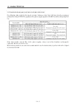
Display Name
Definition
Cause
Action
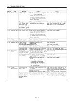
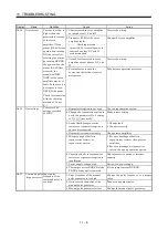
1. Software limit was set within actual
operation range.
Set parameter No. 48 to 51
correctly.
2. Point table of position data in excess of
software limit was executed.
Set point table correctly.
AL.98 Software
limit
warning
Software limit set in
parameter is reached.
3. Software limit was reached during JOG
operation or manual pulse generator
operation.
Perform operation within
software limit range.
AL.9F Battery warning Voltage of battery for
absolute position
detection system reduced.
Battery voltage fell to 3.2V or less.
(Detected with the servo amplifier)
Change the battery.
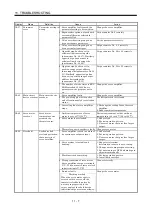
AL.E0 Excessive
regenerative
warning
There is a possibility that
regenerative power may
exceed permissible
regenerative power of
built-in regenerative
resistor or regenerative
option.
Regenerative power increased to 85% or
more of permissible regenerative power of
built-in regenerative resistor or
regenerative option.
Checking method
Call the status display and check
regenerative load ratio.
1. Reduce frequency of
positioning.
2. Change regenerative option
for the one with larger
capacity.
3. Reduce load.
AL.E1 Overload
warning
There is a possibility that
overload alarm 1 or 2
may occur.
Load increased to 85% or more of overload
alarm 1 or 2 occurrence level.
Cause, checking method
Refer to AL.50,51.
Refer to AL.50, AL.51.
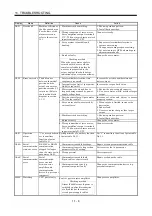
1. Noise entered the encoder.
Take noise suppression
measures.
Absolute position encoder
pulses faulty.
2. Encoder faulty.
Change servo motor.
AL.E3 Absolute position
counter warning
The multi-revolution counter
value of the absolute position
encoder exceeded the
maximum revolution range.
3. The movement amount from the home
position exceeded a 32767 rotation or
37268 rotation in succession.
Make home position setting
again.
AL.E6 Servo forced stop
warning
EMG-SG are open.
External forced stop was made valid.
(EMG-SG opened.)
Ensure safety and deactivate
forced stop.
AL.E9 Main circuit off
warning
Servo was switched on
with main circuit power
off.
Switch on main circuit power.
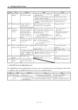
11.3 MR-DP60 external digital display error
When MR-DP60 external digital display detects an error, the following alarms are displayed. The alarms
are displayed only on the MR-DP60, but not on the servo amplifier display.
Display Name
Definition
Cause
Action
AL. CPU CPU error
CPU error
Faulty parts in the MR-D60.
Exchange the MR-D60.
AL. C0
1. CN3 connector disconnected.
Connect correctly.
Communication
error
Communication error
occurred between MR-DP60
and MR-J2S-CP.
2. Wire breakage of the cable.
Repair or exchange the cable.
Содержание MR-J2S-10CP
Страница 11: ...A 10 MEMO ...
Страница 19: ...8 MEMO ...
Страница 45: ...1 26 1 FUNCTIONS AND CONFIGURATION MEMO ...
Страница 181: ...6 20 6 MR Configurator SERVO CONFIGURATION SOFTWARE MEMO ...
Страница 207: ...7 26 7 DISPLAY AND OPERATION MEMO ...
Страница 219: ...8 12 8 GENERAL GAIN ADJUSTMENT MEMO ...
Страница 229: ...9 10 9 SPECIAL ADJUSTMENT FUNCTIONS MEMO ...
Страница 231: ...10 2 10 INSPECTION MEMO ...
Страница 249: ...12 8 12 OUTLINE DIMENSION DRAWINGS MEMO ...
Страница 257: ...13 8 13 CHARACTERISTICS MEMO ...

