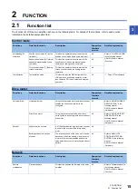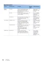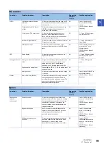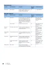
1 SPECIFICATIONS
1.4 Servo amplifier standard specifications
9
1
1.4
Servo amplifier standard specifications
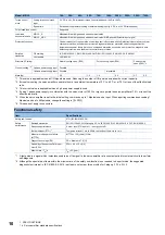
Model: MR-J5-
10A
20A
40A
60A
70A
100A
200A
350A
500A
700A
Output
Voltage
3-phase 0 V AC to 240 V AC
Rated current [A]
1.3
1.8
2.8
3.2
5.8
6.0
11.0
17.0
28.0
37.0
Main circuit power
supply input
Voltage/
Frequency
At AC
input
3-phase or 1-phase 200 V AC to 240 V AC, 50 Hz/
60 Hz
3-phase or 1-
phase 200 V AC to
240 V AC, 50 Hz/
60 Hz
3-phase 200 V AC to 240 V
AC, 50 Hz/60 Hz
At DC
input
283 V DC to 340 V DC
0.9
1.5
2.6
3.2
3.8
5.0
10.5
16.0
21.7
28.9
Permissible
voltage
fluctuation
At AC
input
3-phase or 1-phase 170 V AC to 264 V AC
3-phase or 1-
phase 170 V AC to
264 V AC
3-phase 170 V AC to 264 V
AC
At DC
input
241 V DC to 374 V DC
Permissible frequency
fluctuation
Within ±5 %
Power supply capacity
[kVA]
Refer to "Power supply capacity and generated loss" in the following manual.
MR-J5 User's Manual (Hardware)
Inrush current [A]
Refer to "Inrush currents at power-on of main circuit and control circuit" in the following manual.
MR-J5 User's Manual (Hardware)
Control circuit
power supply
input
Voltage/
Frequency
At AC
input
1-phase 200 V AC to 240 V AC, 50 Hz/60 Hz
At DC
input
283 V DC to 340 V DC
Rated current [A]
0.2
0.3
Permissible
voltage
fluctuation
At AC
input
1-phase 170 V AC to 264 V AC
At DC
input
241 V DC to 374 V DC
Permissible frequency
fluctuation
Within ±5 %
Power consumption [W]
30
Inrush current [A]
Refer to "Inrush currents at power-on of main circuit and control circuit" in the following manual.
MR-J5 User's Manual (Hardware)
Interface power
supply
Voltage
24 V DC ±10 %
Current capacity [A]
0.5 (including CN8 connector signals)
Control method
Sine-wave PWM control, current control method
Dynamic brake
Built-in
Communication
function
USB
Connection to a personal computer or other devices (MR Configurator2-compatible)
Encoder output pulses
Compatible (A/B/Z-phase pulse)
Analog monitor
Two channels
Position control
mode
Max. pulse frequency
4 Mpulses/s (for differential receiver)
, 200 kpulses/s (for open collector)
Positioning feedback pulse
Encoder resolution (resolution per servo motor revolution): 26 bits
Command pulse multiplying
factor
Electronic gear A/B multiple, A:1 to 2147483647, B:1 to 2147483647, 1/10 < A/B < 64000
In-position range setting
0 pulses to ±16777215 pulses (command pulse unit)
Excessive error
±3 revolutions
Torque limit
Set with servo parameter or external analog input (0 V DC to +10 V DC/maximum torque)
Speed control
mode
Speed control range
Analog speed command 1: 2000, internal speed command 1: 5000
Analog speed command
input
0 V DC to ±10 V DC/rated speed (The speed at 10 V is changeable with [Pr. PC12].)
Speed fluctuation ratio
±0.01 % or less (load fluctuation: 0 % to 100 %), 0 % (power fluctuation: ±10 %)
±0.2 % or less (ambient temperature: 25 °C ±10 °C) when using analog speed commands
Torque limit
Set with servo parameter or external analog input (0 V DC to +10 V DC/maximum torque)
Содержание Melservo MR-J5-A
Страница 1: ...MR J5 A User s Manual Introduction MR J5 _A_ Mitsubishi Electric AC Servo System ...
Страница 2: ......
Страница 75: ...6 COMPLIANCE WITH GLOBAL STANDARDS 6 5 Compliance with the China RoHS directive 73 6 MEMO ...
Страница 79: ......


