background image

Air Driven Gas Booster Compressor, 8” Drive AG Series • OM-12J 

1. Introduction 

Information contained in these general Operation and Maintenance Instructions pertain to the 8AG Series 
Air Driven Gas Booster Compressors. Current basic model designations are: 8AGD-1, -2, -2.8, -5, -14, 
 -30, -60, -150 and 8AGT-5/14, -5/30, -14/30, -14/60, -30/60, -30/150, and -60/150. The information will 
also apply to specialized modifications of standard units 

– such as those with special seals or other 

materials for uncommon drive media, gas pumped or environmental conditions; and/or those with special 
port connections, installed accessories, etc., for special purposes. Although these modifications will not 
be covered in detail in these instructions they will be described in detail on the modified assembly/parts 
list, and installation drawings attached to each unit at time of shipment. 

These gas boosters are high flow, air driven, (normally), reciprocating piston type non-lube, oil-free gas 
compressors available in both single stage, double acting (Model 8AGD) and two stage (Model 8AGT) 
configurations. The model dash number is the approximate area ratio of the air drive piston area to gas 
piston area. Thus an 8AGD-5 has a working air drive area of about 5 times the area of either gas piston 
an 8AGT-5/14, an air drive area of about 5 times the area of the first stage and about 14 times the area of 
the second stage. 

2. Description 

2.1 General Principles of Operation 

The air, drive piston in the center of the unit reciprocates automatically powered through the use of a 
nondetented, unbalanced 4-way, air valve spool. This spool valve shifts by being alternately pressurized 
and vented on one end by the pilot air system. The pilot air is controlled by two pilot air valves 
mechanically actuated by the drive piston. This air drive is directly connected to the two gas booster 
section pistons, opposite each other on either end. The gas booster pistons are designed to reciprocate 
dry without lubrication, and to boost inlet gas to desired output - free of hydrocarbon contamination. 

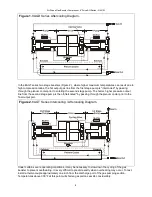
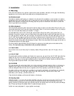
Exhaust from the air drive (chilled due to the expansion after performing work) is used to cool the gas 
piston barrels (through the jackets), and the high pressure output and interstage gas lines (through the 
plenum cooler). 

2.2 Air Drive Section 

Refer to the detailed assembly drawings of the cycling valve and drive section provided with each unit. 
The drive section consists of the drive piston assembly; the unbalanced spool type 4-way cycling valve 
assembly and two pilot stem valves. Porting consists of a drive inlet port, two large exhaust ports; plus 
pilot input, pilot vent and a gauge access port (plugged) into the pilot system. NPT thread is standard. 

One pilot valve is located in the control valve end cap and one in the flow fitting end cap. A flow tube 
connects drive air flow from the valve end cap to the opposite end cap, and a pilot tube connects the two 
pilot valves, which are in series. The cycling spool valve operates without springs or detents and is cycled 
by the pilot valves which alternately pressurize and vent the large area inside the pilot piston inserted in 
the end of the spool valve. The pilot vent exhaust port is in the flow fitting end cap. 

2.2.1 LUBRICATION 

At assembly, light silicone grease (Haskel P/N 50866) is applied to all moving parts and seals (in the drive 
section only-not gas sections). Occasional reapplication of this grease is suggested to the readily 
accessible cycling spool seals depending on duty cycle. See Paragraph 5.2.3.1. Also available is extreme 
service cycling modification No. 54312 which enables continuous operation of the drive without further 
lubrication. 

If not otherwise installed by the factory, always install a conventional bowl type, shop air filter/water 
separator of the same or larger size on the incoming air drive plumbing and maintain it regularly. 

Do not use an airline lubricator. 

2.3 Gas Boosting Section 

Refer to the detailed assembly drawing on the gas pumping section(s) provided with each unit. Each gas 
pumping section consists of a gas barrel with cooling jacket, piston assembly with high pressure dynamic 

Содержание Haskel 8AGD-1

Страница 1: ...OM 12J www haskel com Operating and Maintenance Instructions Air Driven Gas Booster Compressors 8 Drive AG Series 8 8 AG 8 AG...

Страница 2: ...ion and to boost inlet gas to desired output free of hydrocarbon contamination Exhaust from the air drive chilled due to the expansion after performing work is used to cool the gas piston barrels thro...

Страница 3: ...a compression ratio of approximately 25 1 because the inlet check valve will no longer open at any point during the suction stroke to admit fresh gas Therefore applications requiring high compression...

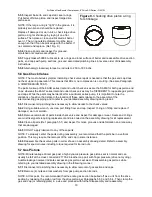
Страница 4: ...her pressure output line from the second stage pump is then aftercooled by passing through the plenum cooler prior to the final output port Figure 2 8AGT Series Intercooling Aftercooling Diagram Under...

Страница 5: ...he drive requires approximately 25 psi to trigger the valve spool and pilot piston as lubricated at the factory It is not necessary or desirable to use an airline lubricator 3 3 1 MUFFLERS For minimum...

Страница 6: ...t parts or plumbing connections NOTE Detailed assembly drawings particular to your specific model have been included as a part of these maintenance instructions Consider these maintenance instructions...

Страница 7: ...aged worn or swollen If any special tools are required it will be noted on the detailed assembly drawing 5 2 3 Reach inside valve body Remove first plastic bumper Carefully pull out spool Inspect 2 sp...

Страница 8: ...seating tool 5 2 9 Repeat installation of remaining parts per paragraph 5 2 3 1 5 3 Pilot Stem Valves NOTE Before repair test according to paragraph 5 4 Disassemble pilot valves in the following manne...

Страница 9: ...essure until pilot valve on cycling valve end is contacted by drive piston and it reverses direction Then gauge will read full pilot air pressure until opposite pilot valve on flow fitting end is cont...

Страница 10: ...assembly drawing during repair 5 6 1 Disconnect all plumbing lines necessary to allow access to the check valves 5 6 2 Using suitable wrench unscrew port fitting from end cap Inspect O ring on fittin...

Страница 11: ...gas barrel bore with a strong light It must be mirror smooth However if only slightly scratched it may be salvaged with a light hone NOTE DO NOT apply a lubricant of any kind to bearings seals O rings...

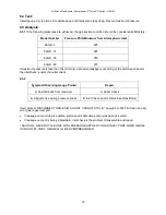
Страница 12: ...ing at the piston seal and or the inlet check and or the outlet check 6 5 2 Symptom Observing Gauge Pointer Repair A Fast fall back from maximum A Outlet Check B Sluggish rise during pressure stroke B...

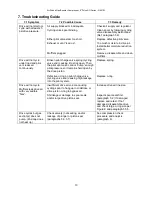
Страница 13: ...sing it to stick open Then the pilot vent valve cannot dump enough pilot pressure so it remains held open by the drive piston Replace spring Defective o ring on pilot charge valve cycling valve end ca...

Страница 14: ...8 OM 12J 14 1 8AG 8AGD 5 14 30 60 8AGT 5 14 5 30 14 60 30 60 8AGD 8AGT 8AGD 5 8AGT 5 14 2 2 1 2 2 NPT 2 2 1 5 2 3 1 54312...

Страница 15: ...8 OM 12J 15 2 3 T 2 3 1 4 25 1 8AGT 8AGD 40 1 10 1 2 3 2 3 1 5 1 10 1 80 C...

Страница 16: ...8 OM 12J 16 1 8AGD 8AGT 2 8AGT 25mm 145 C...

Страница 17: ...8 OM 12J 17 3 3 1 3 2 3 3 19 05 mm 25 4 mm 3 4B 20A 3 4B 20A 1 4B 8A NPT 1 4B 8A NPT 1 8B NPT 1 bar 3 3 1 1 8 m 19 5 mm 3 3 2 1 8B 8A NPT 3 4 3 4B 20A...

Страница 18: ...8 OM 12J 18 3 5 1 2 2 3 4 4 1 1 bar 5 5 1 CV No 242 CV O...

Страница 19: ...8 OM 12J 19 IPA 50 50 5 2 5 2 1 5 2 2 3 O O 4 5 2 3 5 3 4 5...

Страница 20: ...8 OM 12J 20 5 2 3 1 O 2 2 1 6 3 43N m 5 2 4 5 2 1 5 2 3 5 2 5 O 5 2 6 5 2 7 50866 O 5 2 8 O O O O 5 2 9 5 2 3 1 5 3 5 4 5 3 1 6 7...

Страница 21: ...8 OM 12J 21 5 3 2 5 3 3 O 5 3 4 O 50866 5 3 5 5 3 6 O O 5 3 7 50866 5 4 5 4 1 17568 2 5 4 2 0 11 bar 1 8B 5 4 3 8...

Страница 22: ...8 OM 12J 22 O 5 3 6 5 5 5 5 1 5 5 2 5 5 3 5 5 4 E O 5 5 5 O O O O O O 5 5 6 5 5 7 50866 O 5 5 8 28 4 34 3N m 5 6 8AGD 8ADT 5 6 1 9 O...

Страница 23: ...8 OM 12J 23 5 6 2 O 5 6 3 O 5 6 4 5 1 5 6 5 5 6 6 5 7 21703 2 5 7 1 5 7 2 5 5 3 5 5 4 5 7 3 O 5 7 4 O O 5 7 5 O 5 7 6 5 1 5 7 7...

Страница 24: ...8 OM 12J 24 O 5 7 8 5 7 9 6 6 1 6 2 70 bar 6 3...

Страница 25: ...8 OM 12J 25 6 4 6 5 6 5 1 bar 8AGD 5 15 5 8AGD 14 15 5 8AGD 30 17 2 8AGD 60 21 7 6 5 2 A A B B B 5 5 34 5 bar...

Страница 26: ...8 OM 12J 26 7 7 1 7 2 7 3 1 4 bar 5 2 O O O 9 5 5 5...

Страница 27: ...8 AG OM 12J 27 1 8AG 8AGD 5 14 30 60 8AGT 5 14 5 30 14 30 14 60 30 60 1 8AGD 2 8AGT 8AGD 5 5 8AGT 5 14 1 5 2 14 2 2 1 4 2 2 2 2 4 2 2 NPT 1 1 2 2 2 1 Haskel 28442 5 2 3 1 54312...

Страница 28: ...8 AG OM 12J 28 2 3 T 1 2 2 3 1 psi 0 4 25 1 0 2 8AGT 2 8AGD Haskel 40 1 10 1 2 3 2 3 1 5 1 10 1 150 F...

Страница 29: ...8 AG OM 12J 29 8AGD 8AGT 8AGD 1 2 1 1 8AGD 8AGT 2 2 1 2 2 2 8AGT...

Страница 30: ...8 AG OM 12J 30 1 in 300 F 3 3 1 3 2 3 3 3 4 1 3 4 3 4 NPT 1 4 NPT 1 4 NPT 1 8 NPT 15 psi 3 3 1 6 ft 3 4 3 3 2 1 8 NPT 3 4 3 4...

Страница 31: ...8 AG OM 12J 31 3 5 1 2 2 3 4 4 1 15 psi 5 5 1 Loctite CV Blue 242 Loctite CV O...

Страница 32: ...8 AG OM 12J 32 Stoddard 50 50 5 2 5 2 1 4 5 2 2 3 O O 4 3 4 Pilot shaft end seal...

Страница 33: ...8 AG OM 12J 33 5 2 3 2 5 5 2 3 1 O 2 2 1 6 4 30 in lb 5 2 4 5 2 1 5 2 3 7 5 2 5 4 O 5 2 6 5 2 7 O Haskel 28442 5 2 8 O 2 O O 4 O 5 2 9 5 2 3 1 5 6 7...

Страница 34: ...8 AG OM 12J 34 5 3 5 4 5 3 1 5 3 2 5 3 3 2 O 5 3 4 O Haskel 28442 5 3 5 5 3 6 O O 2 8 Tru Arc 5 3 7 Haskel 28442 5 4 5 4 1 17568 2 5 4 2 1 8 NPT 0 160 psi 5 4 3 O 8...

Страница 35: ...8 AG OM 12J 35 5 3 6 5 5 5 5 1 5 5 2 5 5 3 4 8 5 5 4 1 E 1 1 O 5 5 5 O O O O 9 5 5 6 5 5 7 O Haskel 28442 5 5 8 250 300 in lb 5 6 6 8AGD 2 8AGT 5 6 1 5 6 2 O 9 O...

Страница 36: ...8 AG OM 12J 36 5 6 3 O 5 6 4 5 1 5 6 5 5 6 6 5 7 21703 2 5 7 1 5 7 2 4 5 5 3 5 5 4 5 7 3 O 5 7 4 O O 5 7 5 O 5 7 6 5 1 5 7 7 O 5 7 8 5 7 9 6 6 1...

Страница 37: ...OM 12J 37 6 2 1000 psig 6 3 6 4 Install gauge Cycle drive at moderate speed until pressure stops rising Record maximum pressure 6 5 6 5 1 psig 8AGD 5 225 8AGD 14 225 8AGD 30 250 8AGD 60 315 6 5 2 A A...

Страница 38: ...8 AG OM 12J 38 B 80 500 psi 7 7 1 7 2 7 3 20 psi 5 2 O O 9 5 5 6 O 6...

Страница 39: ...8 AG OM 12J 39 1 8 AG 8AGD 5 14 30 60 8AGT 5 14 5 30 14 30 14 60 30 60 8AGD 8AGT 8AGD5 5 8AGT5 14 5 14 2 2 1 4 2 2 4 NPT T T 2 2 1 Haskel p n 28442 5 2 3 1 54312 2 3...

Страница 40: ...8 AG OM 12J 40 I 2 2 3 1 psi 0 25 1 4 0 2 8AGT 2 8AGD Haskel 40 1 10 1 2 3 2 3 1 5 1 10 1 150 F 8AGD 8AGT 8AGD 1...

Страница 41: ...8 AG OM 12J 41 1 8AGD 8AGT 2 2 8AGT 1 300 F...

Страница 42: ...8 AG OM 12J 42 3 3 1 3 2 3 3 3 4 1 3 4 3 4 npt 1 4 npt 1 4 npt 1 8 npt 15 psi 3 3 1 6 3 4 3 3 2 T 1 8 npt 3 4 3 4 3 5 1 2 2 3 4...

Страница 43: ...8 AG OM 12J 43 4 1 15 PSI 5 5 1 Loctite CV 242 Loctite CV O 50 50 5 2 5 2 1...

Страница 44: ...8 AG OM 12J 44 5 2 2 3 O O 4 5 2 3 5 5 2 3 1 O 2 2 1 6 30 5 2 4 5 2 1 5 2 3 3 4 5 6...

Страница 45: ...8 AG OM 12J 45 7 5 2 5 4 O 5 2 6 5 2 7 Haskel 28442 O 5 2 8 O O O 4 O 5 2 9 5 2 3 1 5 3 5 4 T 5 3 1 T 5 3 3 T T O 5 3 4 O 28442 5 3 5 5 3 6 T O O T 7 8...

Страница 46: ...8 AG OM 12J 46 Tru Arc 8 5 3 7 Haskel 28442 5 4 5 4 1 p n 17568 2 5 4 2 1 8 NPT 0 160 PSI 5 4 3 T O T 5 3 6 5 5 5 5 1 5 5 2 T 5 5 3 4 8 5 5 4 E O 9 O...

Страница 47: ...8 AG OM 12J 47 5 5 5 O O O O 9 5 5 6 5 5 7 Haskel 28442 O 5 5 8 250 300 5 6 6 8AGD 8AGT 5 6 1 5 6 2 O 5 6 3 O 5 6 4 5 1 5 6 5 5 6 6 5 7 21703 2 5 7 1 5 7 2 5 5 3 5 5 4...

Страница 48: ...8 AG OM 12J 48 5 7 3 O 5 7 4 O O 5 7 5 O 5 7 6 5 1 5 7 7 O 5 7 8 5 7 9 6 6 1 6 2 1000 PSlG 6 3...

Страница 49: ...8 AG OM 12J 49 6 4 6 5 6 5 1 PSlG 8AGD 5 225 8AGD 14 225 8AGD 30 250 8AGD 60 315 6 5 2 A A B B B 80 500 PSI...

Страница 50: ...8 AG OM 12J 50 7 7 1 7 2 7 3 20 psi 5 2 O O 9 5 5 5 O 6...

Страница 51: ...ance for lifting e Safety labels on the machines and meanings are as follows General Danger Read Operator s Manual f In an emergency turn off the air supply g Warning If the pump s were not approved t...

Страница 52: ...ranty claim and to expedite the return of replacement to the owner If unit has been disassembled or reassembled in a facility other than Haskel warranty is void if it has been improperly reassembled o...

Отзывы: