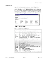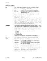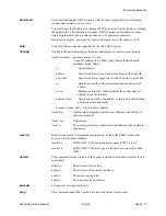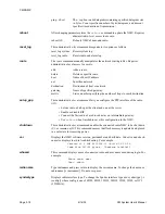
CM SNMP
Page F-6
6/14/02
CM System User’s Manual
Connecting Cables
After installing the CM radio, connect cables from your Ethernet network to the radio
and make the following connections as this section details.
• 10BaseT port to the network
• Network interface SCE port to the radio SCE connector
• Maintenance terminal to the local access port (if required)
Ethernet (10BaseT) Port
10BaseT cabling is 10-MHz Ethernet running over un-shielded twisted-pair cable. Its
maximum length is generally 100 to 150 meters, but length limits are based on signal
loss in decibels (11.5db max.). The connection is RJ45 for interfacing radio alarms and
controls through a network. When connecting the radio to a hub, wire 10BaseT cables
(Category 3 or better) straight through. When connecting directly to a network, or the
radio Ethernet connections at repeater sites, cross-pin cables. Table F-G lists cable
pinning.
SCE Port
The SCE Network port bridges alarm and control data normally connected to an SCE
unit. The bridge cable, PN 8108633-02, is RJ11 4-wire-to-RJ11 4-wire with straight-
through pinning. Table F-H lists pin assignments.
The SCE,
Status & Control Extender
, uses alarm/control relays to provide system
alarm, status, and performance information to and controls from remote alarm moni-
toring equipment.
Table F-G. Ethernet Port Pins
Pin
Signal
Color
1
TX +
White/Orange
2
TX -
Orange
3
RX +
White/Green
4
Blue
5
White/Blue
6
RX -
Green
7
White/Brown
8
Brown
Figure F-4. Network Interface Ports
Access-Panel
Jack
Cable connections
Содержание CM7
Страница 2: ......
Страница 4: ...Page iv 5 04 05 CM7 8 100Base T System User s Manual ...
Страница 16: ...Glossary Page xvi CM System Users Manual X Y Z ...
Страница 24: ...Microwave Networks CM7 8 100Base T System User s Manual Pagexxiv ...
Страница 62: ...Chapter 2 Operation Page 2 18 5 02 05 CM 100Base T System User s Manual ...
Страница 64: ...Chapter 3 Module Descriptions Page 3 2 CM7 8 100Base T ...
Страница 88: ...Section 3 3 Transmitter Unit Page 3 3 6 CM7 8 System User s Manual ...
Страница 96: ...Section 3 5 RF Power Supply Unit Page 3 5 4 CM System User s Manual ...
Страница 100: ...Section 3 6 SP Power Supply Unit Page 3 6 4 CM System User s Manual ...
Страница 106: ...Section 3 7 Alarm and Control Unit Page 3 7 6 11 18 03 CM 100Base T System User s Manual ...
Страница 124: ...Section 3 11 SYNDES Page 3 11 6 CM System User s Manual ...
Страница 130: ...Section 3 12 SCU Page 3 12 6 11 18 03 CM 100Base T System User s Manual ...
Страница 138: ...Section 3 13 OWU Page 3 13 8 CM System User s Manual ...
Страница 150: ...Section 3 15 NMU Page 3 15 6 CM System User s Manual ...
Страница 192: ...Chapter 5 Verification Page 5 20 CM System User s Manual ...
Страница 194: ...Chapter 6 Maintenance Page 6 2 7 23 03 CM 100Base T System User s Manual ...
Страница 224: ...Chapter 6 Maintenance Page 6 32 7 23 03 CM 100Base T System User s Manual ...
Страница 225: ...CM System User s Manual Page 1 Place any site research or reference material here Site Engineering ...
Страница 226: ...Site Engineering Page 2 CM System User s Manual ...
Страница 230: ...Appendix A T I Curves Page A 4 CM7 8 100Base T System User s Manual ...
Страница 267: ...Microwave Networks CM System User s Manual PageB 37 ...
Страница 268: ...Appendix B QuikLink Page B 38 CM System User s Manual ...
Страница 282: ...Appendix D Alarm Codes Page D 6 5 02 05 CM 100Base T System User s Manual ...
Страница 290: ...Appendix E Setting Frequency Page E 8 CM7 8 System User s Manual ...
Страница 312: ...CM7 8 100Base T System User s Manual Page I 4 Microwave Networks ...


