


Microwave Networks
CM System Users Manual
Page B-15
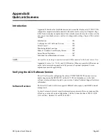
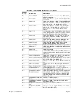
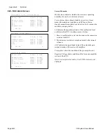
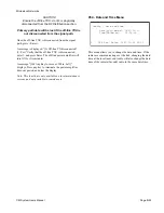
022 - SYNDES Alarm Screen
Screen Elements
Module Status indicates whether the module is operating
normally (Normal) or is in alarm (Alarm.)
Service Status shows absent, standby, in-service.
Absent
means the module is required but not installed or an SP
fuse is blown.
Standby
means the module is present but not
in service.
In-Svc
means the module is carrying traffic.
Transmit and receive status shows a failure in either the
transmit path or receive path. The path status that has the
highest priority according to the list below is used as the
composite module state.
1. Missing module or empty slot.
2. Alarm
3. In-Svc
4. Standby
5. Normal
Switch Confirm
shows when the SYNDES fails to respond
to a switch command on protected systems.
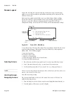
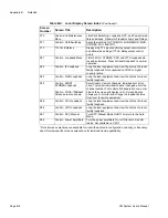
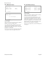
If the DS1 signal is absent at the line interface circuit for
any channel configured as equipped, the appropriate alarm
activates.
If any of the RX portion of the SYNDES is in alarm for a
particular channel, the appropriate alarm activates.
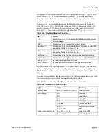
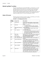
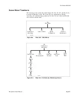
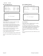
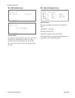
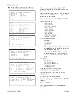
DS3 Configurations
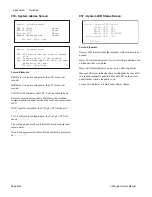
Input BER
alarm indicates the bit error rate at the DS3 input
exceeds 10
-6
LOS at DS3 Input
alarm is a loss of signal at the DS3 input
to the SYNDES.
LOS at DS3 Output
alarm is a loss of signal at the DS3
output from the SYNDES.
DS3 Rx PLL
indicates receive side phase lock loop circuit
has failed or is out of range.
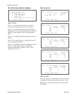
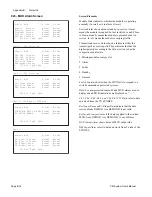
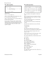
L 022 Esc PgUp PgDn
Alarm - SYNDES A Side B Side
Module Status: Alarm Alarm
Service Status: In-Svc Standby
Transmit Status: Normal Normal
Receive Status: Normal Normal
Switch Confirm: Alarm Normal
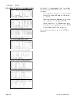
Page 2. DS1 Protected
L 022 Esc PgUp PgDn
Alarm - SYNDES
28 DS1 Input LOS:
A Side
B Side
1 5 - 13 17 21 25
1 5 - 13 17 21 25
2 6 10 14 - 22 26
2 6 10 14 - 22 26
- 7 11 15 19 23 27
- 7 11 15 19 23 27
4 8 12 16 20 - 28
4 8 12 16 20 - 28
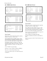
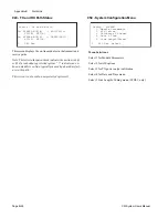
Alarm - SYNDES A Side B Side
DS1 Ch1-Ch4 Input: Normal Normal
DS1 Ch5-Ch8 Input: Normal Normal
DS1 Ch9-Ch12 Input: ------ ------
DS1 Ch1-Ch4 Output: Normal Alarm
DS1 Ch5-Ch8 Output: Normal Normal
DS1 Ch9-Ch12 Output: ------ ------
L 022 Esc PgUp PgDn o
Page 2. 28 DS1 Protected
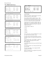
Alarm - SYNDES A Side B Side
DS3 Ch1 Input: Normal Normal
DS3 Ch2 Input: Normal Normal
DS3 Ch3 Input: ------ ------
DS3 Ch1 Output: Normal Alarm
DS3 Ch2 Output: Normal Normal
DS3 Ch3 Output: ------ ------
L 022 Esc PgUp PgDn o
Page 2. DS3 Protected
L 022 Esc PgUp PgDn
Alarm - SYNDES A Side B Side
DS3 Input BER: Normal Normal
LOS at DS3 Input: Normal Normal
LOS at DS3 Output: Normal Alarm
DS3 Rx PLL: Normal Normal
Page 2. 3 DS3 Protected
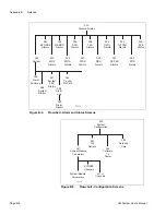
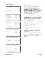
Page 2. 155-Mbps or 100BaseT
L 022 Esc PgUp PgDn
Alarm - SYNDES A Side B Side
SONET/SDH INPUT LOS: Normal Normal
SONET/SDH RX PLL: Normal Normal
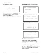
P
a
g
e
2
.
1
0
0B
as
e
T
L
0
2
2
E
s
c Pg
U
p P
g
Dn
A
l
a
r
m
-
S
Y
ND
E
S
A
S
id
e
B
Si
d
e
P
D
H
I
NP
UT
LO
S
:
N
or
m
al
No
r
ma
l
P
D
H
R
X
PL
L
:
N
or
m
al
No
r
ma
l
R
E
C
M
UX
C
L
OC
K
:
N
or
m
al
No
r
ma
l
R
E
C
E
I
VE
F
R
AM
E
:
N
or
m
al
No
r
ma
l
Содержание CM7
Страница 2: ......
Страница 4: ...Page iv 5 04 05 CM7 8 100Base T System User s Manual ...
Страница 16: ...Glossary Page xvi CM System Users Manual X Y Z ...
Страница 24: ...Microwave Networks CM7 8 100Base T System User s Manual Pagexxiv ...
Страница 62: ...Chapter 2 Operation Page 2 18 5 02 05 CM 100Base T System User s Manual ...
Страница 64: ...Chapter 3 Module Descriptions Page 3 2 CM7 8 100Base T ...
Страница 88: ...Section 3 3 Transmitter Unit Page 3 3 6 CM7 8 System User s Manual ...
Страница 96: ...Section 3 5 RF Power Supply Unit Page 3 5 4 CM System User s Manual ...
Страница 100: ...Section 3 6 SP Power Supply Unit Page 3 6 4 CM System User s Manual ...
Страница 106: ...Section 3 7 Alarm and Control Unit Page 3 7 6 11 18 03 CM 100Base T System User s Manual ...
Страница 124: ...Section 3 11 SYNDES Page 3 11 6 CM System User s Manual ...
Страница 130: ...Section 3 12 SCU Page 3 12 6 11 18 03 CM 100Base T System User s Manual ...
Страница 138: ...Section 3 13 OWU Page 3 13 8 CM System User s Manual ...
Страница 150: ...Section 3 15 NMU Page 3 15 6 CM System User s Manual ...
Страница 192: ...Chapter 5 Verification Page 5 20 CM System User s Manual ...
Страница 194: ...Chapter 6 Maintenance Page 6 2 7 23 03 CM 100Base T System User s Manual ...
Страница 224: ...Chapter 6 Maintenance Page 6 32 7 23 03 CM 100Base T System User s Manual ...
Страница 225: ...CM System User s Manual Page 1 Place any site research or reference material here Site Engineering ...
Страница 226: ...Site Engineering Page 2 CM System User s Manual ...
Страница 230: ...Appendix A T I Curves Page A 4 CM7 8 100Base T System User s Manual ...
Страница 267: ...Microwave Networks CM System User s Manual PageB 37 ...
Страница 268: ...Appendix B QuikLink Page B 38 CM System User s Manual ...
Страница 282: ...Appendix D Alarm Codes Page D 6 5 02 05 CM 100Base T System User s Manual ...
Страница 290: ...Appendix E Setting Frequency Page E 8 CM7 8 System User s Manual ...
Страница 312: ...CM7 8 100Base T System User s Manual Page I 4 Microwave Networks ...


